Please look at the main entry for more information on how to prepare the ROM file!
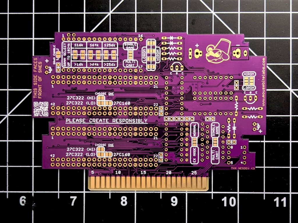
Here I will detail to you a guide to making SNES games using my custom boards. These boards differ from other designs, including my basic board, in that there are TWO EPROM sockets, and they support the 27C322 and 27C160 EPROMs. That gives you the ability to:
- Make a normal game up to 2 MB (16 Mbit) with one 27C160 EPROM
- Make a normal game up to 4 MB (32 Mbit) with one 27C322 EPROM
- Make an ExHiROM or ExLoROM game up to ~8 MB (64 Mbit) split across two 27C322 EPROMs (or a 6 MB game with one 27C322 and one 27C160)
- Make a multi-cart with two games up to 4 MB (32 Mbit) each, with up to 512K SRAM available for each game
I will discuss the hardware needed for the board – I will not be going over how to prepare the ROM file. Check out the main tutorial to determine those details. And it is important to note, these boards cannot be used to replicate games that used specialty chips on their boards – this means you cannot make games that require: SuperFX, SuperFX2, DSP chips, SA-1, C4, S-DD1, or SPC7110.
All the details for the parts you will need to make a board are shown below, including where to buy the parts and part numbers. I also made a video to go along with this board where I make an ExHiROM game, as an example. Check it out if you’d like!
Parts Needed (topside)
Here’s a breakdown of what parts you need based on what kind of game you’re making. All parts are located on the front of the board (but you can generally put the discrete parts on the back of the board as well). For the discrete parts, other than capacitors (includes resistors, diodes, and the transistor) there are both surface mount pads and through-hole sockets available. Each part will include the value or part number, and examples of where to buy them. All the parts I suggest below will be through-hole, but for some parts there are surface mount pads available if you’d rather use those.
Note: especially for discrete parts (resistors/caps/diodes) you can safely buy most or all of these parts on eBay or AliExpress for generally lower prices (with usually longer shipping times). The highest quality parts, though, will come from distributors or manufacturers. Therefore, I will generally be providing links to the parts from Digikey and Mouser, as that is where I buy most of my parts.
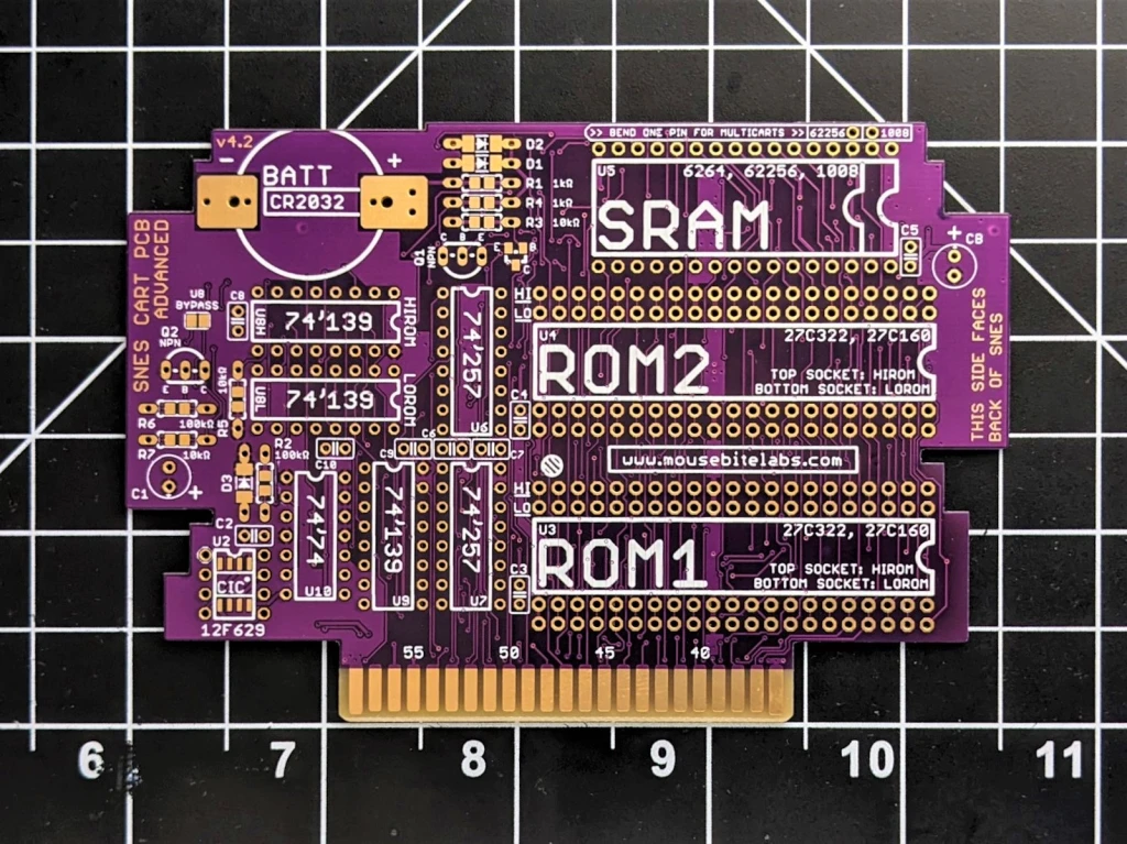
U3, U4 – ROM1, ROM2 (EPROM)
Needed for: Every game
Part Number: 27C160 or 27C322
Example Part: Search for them on eBay or AliExpress – these are older parts, they are not made new anymore. Because they are old parts, you run a slight risk of getting some defective ones. It’s not generally possible to find “reputable” sellers of them, so if you find that you have some defective parts, you just have to ask for a refund for the non-working ones.
Function: Holds the ROM file(s); use the #1 slot for games that only use one EPROM, additionally use the #2 slot for ExHiROM/ExLoROM games and multicarts.
How to Program: Check the reproduction article for more information (Steps 1, 5, 6, and 7)
C1 – Electrolytic Capacitor
Needed for: Every game
Value: ~22 uF, at least 10 V rated
Example Part: Here is an example part from Digikey. Just make sure to get the right value and rating – note that if it is too tall, you might have to bend it down to sit flat on the board so it fits inside the cartridge.
Function: Smooths out supply voltage for the board due to transients on the power supply, prevents quick changes in supply voltage when power is turned off.
CB – Electrolytic Capacitor
Needed for: Games that save
Value: ~22 uF, at least 10 V rated
Example Part: Same as C1.
Function: Prevents transient voltage drops on the SRAM during power-down.
C2, C3, C4, C6, C7, C9 – Ceramic Capacitors
Needed for: Every game (C4 only required if you use second EPROM)
Value: ~0.1 uF, at least 10 V rated
Example Part: Here is an example part from Digikey.
Function: Filters out high-frequency noise that can interrupt the function of the chips on the board.
C5, C8 – Ceramic Capacitors
Needed for: Games that save
Value: ~0.1 uF, at least 10 V rated
Example Part: Same as previous ceramic capacitors.
Function: Filters out high-frequency noise that can interrupt the function of the chips on the board.
C10 – Ceramic Capacitor
Needed for: Multicarts
Value: ~0.1 uF, at least 10 V rated
Example Part: Same as previous ceramic capacitors.
Function: Filters out high-frequency noise that can interrupt the function of the chips on the board.
CIC – Region Lock-out Chip
Needed for: Every game (on un-modded SNES systems)
Part Number: PIC12F629
Example Part: Here’s a page from Digikey and Mouser. Sometimes this part is out of stock here, and you have to resort to eBay, but beware that you might get a few defective parts.
Function: Replaces the region lock-out chip used in the SNES to let you play the game.
Click here to jump to Step 9g of the main SNES tutorial to find out how to program the CIC, if yours isn’t pre-programmed
R1, D1, D2 – Resistor and Diodes
Needed for: Games that save
Value: 1 kΩ for R1, low reverse leakage diodes (BAT85 or 1N4148) for D1 and D2
Example Part: Here’s an example resistor and diode from Digikey, and a diode from Mouser.
Function: Combines the battery and SNES voltage rails to power the SRAM and keep it working after the SNES power is turned off. To lengthen save data retention, it’s better to get diodes that have a low reverse leakage.
R3, R4, Q1 – Resistors and NPN Transistor
Needed for: Games that save
Value: 1 kΩ for R4, 10 kΩ for R3, 2N3904 for Q1
Example Part: Here’s a transistor from Digikey.
Function: Puts the SRAM into a low-power state during power-off.
R2, R5, D3 – Resistors and Diode
Needed for: Games that save
Value: 100 kΩ for R2, 10 kΩ for R5, same diodes as D1 and D2 for D3
Example Part: Same as earlier parts.
Function: Adds save glitch protection. D3 keeps /RESET from staying high while the supply voltage drops. R2 is a pull-down resistor on the /RESET line. R5 stops erroneous operation of Q1 from leakage current out of U8 decoder.
R6, R7, Q2 – Resistors and NPN Transistor
Needed for: Games that utilize an AS6C1008 SRAM chip (U5)
Value: 100 kΩ for R6, 10 kΩ for R7, 2N3904 for Q2
Example Part: Same as earlier parts.
Function: Adds a load to the SRAM supply pin. There are protection diodes internal to the AS6C1008 (not present on other AS6C SRAM models) that causes noise to rectify onto the supply line. Because the load is too light, this voltage can float above the recommended operating limits for the chip. The circuit made by these three parts adds a small load to the supply to discharge the rectified noise. You do not need these parts if you are using an SRAM chip other than the AS6C1008.
B1 – Battery
Needed for: Games that save
Part Number: CR2032
Example Part: I commonly buy these pre-tabbed from eBay, but buying from Digikey or Mouser will probably give you higher quality longer-lasting batteries (be sure if you buy non-tabbed batteries to also get a battery holder – do not try soldering tabs onto batteries yourself).
Function: Keeps the SRAM on to retain data while power is off.
U5 – SRAM
Needed for: Games that save
Part Number: 6264 (64K), 62256 (256K), or 1008 (1024K) series SRAM (be sure to get low standby current model)
Example Part: If you have a choice, I recommend getting an SRAM chip as close to the amount you need. The AS6C1008 will be large enough for any game, but the AS6C62256 covers nearly all of them as well. The AS6C6264 works for games that have 64Kbit of SRAM, but they don’t work for multicarts (on my board). These SRAM chips also have a low data retention current, which is good for longer save battery life, but my tests show that generally the AS6C1008 has a higher data retention current than the AS6C62256 or the AS6C6264. A higher data retention current means your save data will be erased sooner (but should be safe for many years regardless). Also, as mentioned earlier, the AS6C1008 requires R6, R7, and Q2 to be included on the board. So you should stick to the 6264 or 62256 if possible.
Function: Holds save game data.
How to Determine Data Retention Current: If you have a multimeter, put it into DC millivolt mode and carefully measure across the terminals of R1. You should read a voltage somewhere in the single to fraction of a mV. Testing the chips I have in my stock, I usually read about 0.4 mV for 62256 SRAM chips and 1.6 mV for 1008 SRAM chips. You can calculate data retention current from this measurement with Ohm’s Law – V=IR. V (voltage) is this measurement on the multimeter, R is the resistance of R1 (1 kΩ) and I is the data retention current. So for the 62256 SRAM, I get a data retention current of 0.0000004 A, or 0.4 uA (microamps). For 1008 SRAM, I get 1.6 uA.
U6, U7 – Multiplexers
Needed for: Every game
Part Number: 74HCT257 or 74LS257 are recommended (74HC257 should be fine as well)
Example Part: Digikey has all of the 74 series logic, but you might also be able to get them from TI directly.
Function: Maps the data from the 27C160 or 27C322 (which uses a 16-bit bus) to the SNES cartridge (which uses an 8-bit bus).
U9 – Decoder (bottom-most)
Needed for: Every game
Part Number: 74HC139 (or equivalent)
Example Part: Digikey has all of the 74 series logic, but you might also be able to get them from TI directly.
Function: Tells the multiplexers when to output data; switches between EPROM #1 and #2 for either Ex-mode games, or for multicart functionality.
U8 – SRAM Decoder (middle of board, choose only one for LoROM or HiROM)
Needed for: Games that save
Part Number: 74HC139 (or equivalent)
Example Part: Same as U9.
Function: Activates the ROM or RAM, depending on the memory address being accessed. U8L is populated for LoROM games, U8H is populated for HiROM games. You can put parts in both sockets if you want, the board will still work.
U10 – Flip-Flop
Needed for: Multicart boards
Part Number: 74HC74 (or equivalent)
Example Part: Like U6-U9, Digikey carries them.
Function: Switches between EPROM #1 and #2 when the reset button is pressed on the console.
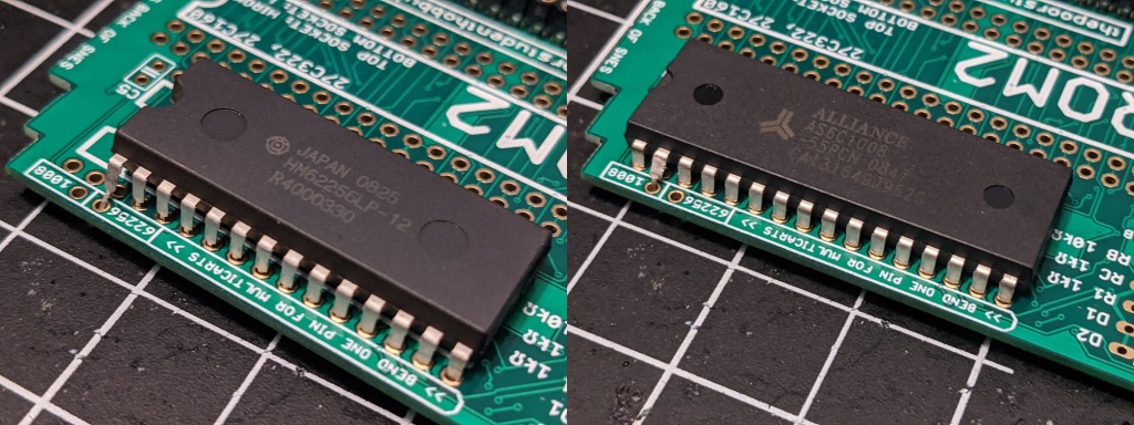
Multicart Socket
If you plan on making a multicart with games that require SRAM, then you need to kink one of the legs out and solder to the proper socket, as indicated on the board. If using a 62256 SRAM chip, bend out pin 1. If using a 1008 SRAM chip, bend out pin 2.
Solder Pad (frontside)
There is only one set of solder pads on the front of the board.
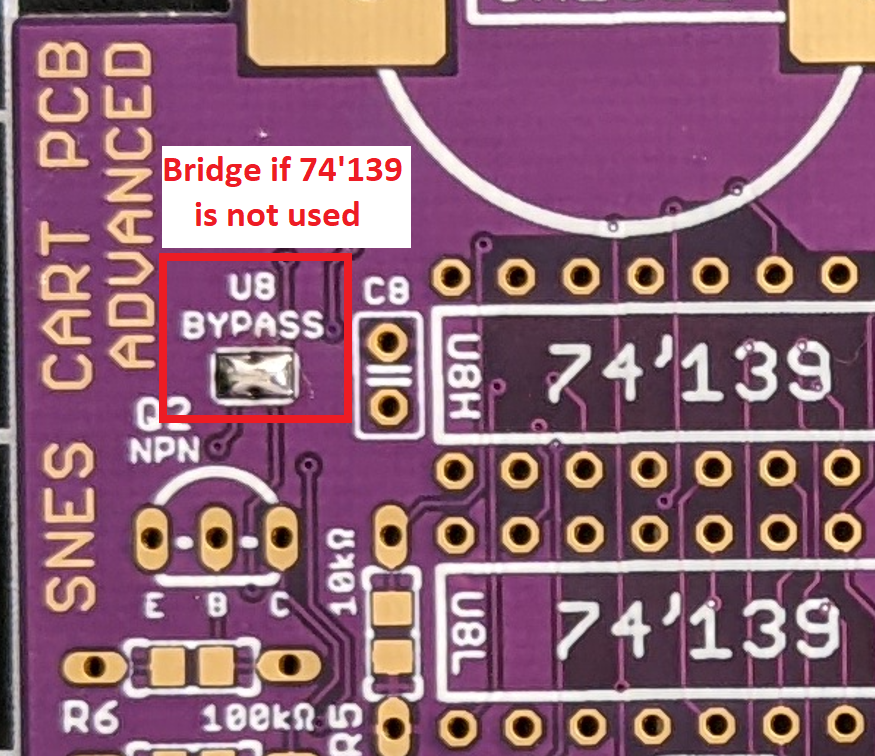
Decoder Bypass
Shorted: Enables output on boards without SRAM or the SRAM decoder
Open: Does nothing (do not short unless you do not have an SRAM decoder)
Solder Pads (backside)
There are a handful of solder pads you’ll need to bridge on the back of the board in order to make your game work.
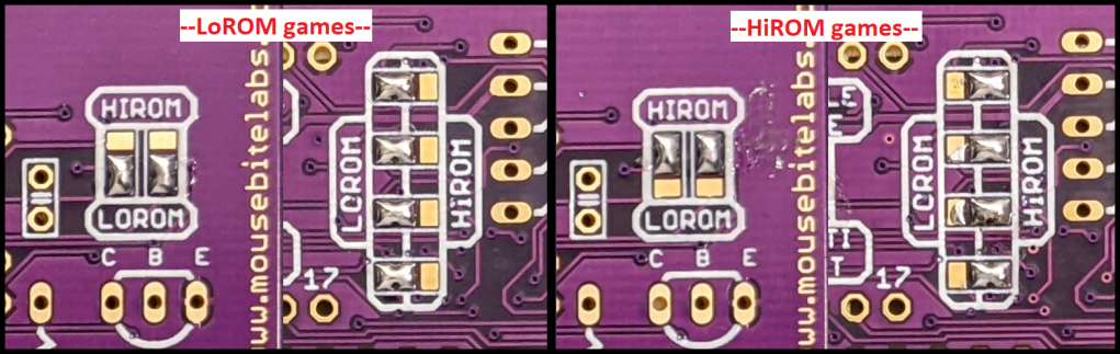
HiROM/LoROM Selection
There are a few sets of three-way solder pads located in various locations on the board. You need to bridge two of the three depending on what bank type your game(s) is/are. Note that this bank selection will apply to both EPROM #1 and EPROM #2, if you’re using both (can’t make a multi-cart with one LoROM and one HiROM game).
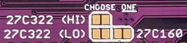
27C322 or 27C160 EPROM Selection
For each EPROM #1 and #2, you can use either a 27C322 or 27C160. You must bridge the solder pad pair of the type you are using for each socket. If you’re using a ‘322, you must also choose either Lo or HiROM as well.
If you’re not making an Ex-mode game, or a multicart, then you only need to solder pads behind the ROM1 socket.
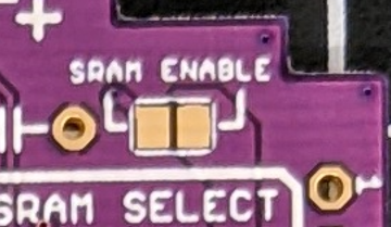
SRAM Enable
If you’re using SRAM, in the top left corner of the board bridge these pads together. If you reprogram your EPROM with a new game, you should disconnect these pads by desoldering them to reset the SRAM (they only need to be disconnected for a second). Then, resolder them together for your new game.
SRAM SIZE (SRAM selection pads)
These are another set of three-way solder pads, located in the top middle of the board. You need to bridge the set of pads (the middle and one to the top or bottom) depending on the size of the SRAM your game uses. Similar to the pads above, solder the two in the direction of the size of SRAM your game uses.
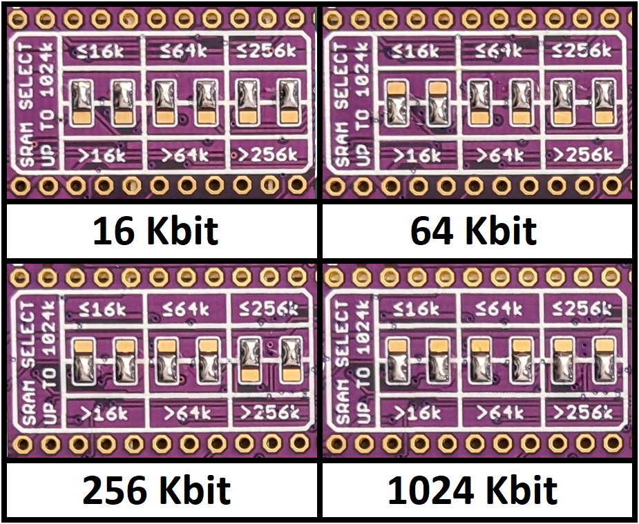
NOTE: If you make a multi-cart game, your SRAM size will be at most half of the full size of the SRAM chip. So for a 256 Kbit SRAM chip in multicart mode, the max available SRAM size will be 128 Kbit. Both games will have the same amount of SRAM – you can’t make one game have 16 Kbit SRAM and the other 256 Kbit, for example.
Mode Selection
There are three “mode selection” solder pads. These are for selecting between a normal game layout, EX mode (or expanded mode), or multicart mode.
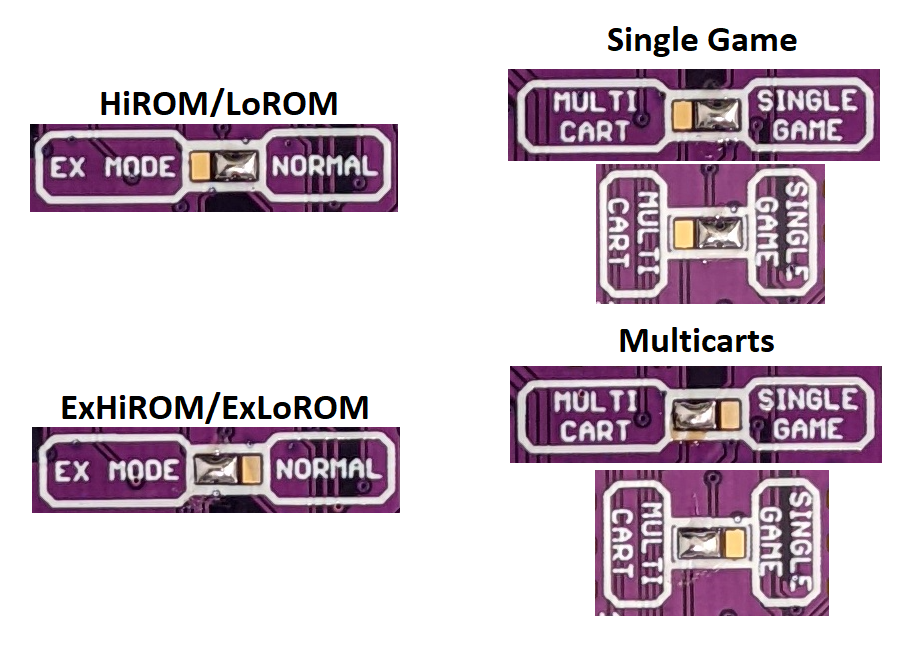
“EX mode” on my board just means any game that requires more than one 27C322. So ExHiROM and ExLoROM games, or just HiROM/LoROM games that take up more space than 32 Mbits. This is a not-so-important distinction, but many ROM hacks (and official re-releases) that expand the memory used of the usually HiROM game don’t actually count as ExHiROM, or Mode 25. They still operate in Mode 21, and you cannot simply use a true ExHiROM configuration for these larger HiROM games. Luckily, my board supports both types if you set it to EX mode!
Note that you cannot have EX mode and multicart mode enabled, because multicart mode switches between two games that use one ROM socket each.
Furthermore, if you are making a multicart, you must use the same mapper type for both (LoROM or HiROM). You cannot mix bank types between games.

How to flash 2 Eprom with TL866 for exHirom game?
Do I have to split original file and program one by one all banks?
For example : Eprom 1 (banks 0-7), Eprom 2 (banks 8-16).
LikeLike
Yep
LikeLike
I’ve put together my test board for this but am having issues with a black screen on startup. I’m using a homemade programmer (a side project I’m working on) for both the EPROM and superCIC chips, which I feel might be the cause of issue, but I’m struggling to identify if its a problem with the CIC chip or the EPROM.
Before I got my hands on the CIC chip (or when I use a blank one), my tv doesnt even go past the idle screen. With the CIC chip installed I instead get a lit black screen, a slight flicker, and then a drop to a darker back screen with no change after that. I’m using a headerless ROM of link to the past, with my test card set up for lowROM and all the jumpers seemingly in the right place but I’ve had zero luck!
My EPROM programmer verifies the programmed data matches that of the original ROM, and a dumped copy of the ROM runs fine in an emulator, so I’m struggling to find answers
Any tips on what I could do to debug if this is a programming issue or a hardware issue would be very welcome
LikeLike
Scratch that, I finally figured it out
Not only was i writing with the wrong endian, I was writing the most significant bit to the Q0 pin, everything works great now!
LikeLike
Oh, nice!! Haha good job!
Fwiw on my television, it will say “no signal” if the CIC doesn’t work, and just a black screen if the ROM is bad but the CIC is fine
LikeLike
Is there anywhere I can get the gerbers for this board? I can think of improvements to make to this board, but they’d also make it bigger, to make room for several through hole double pole switches. why? rom chip and sram testing with sockets, and needing to redo soldering on smt components constantly is probably the most amount of pain I could ask for.
LikeLike