Please look at the main entry for more information on how to prepare the ROM file!
Here’s a quick guide on how to populate my custom designed NES reproduction PCB. This is the “Discrete” version that supports AxROM, BNROM, CNROM, GNROM, NROM, and UxROM games.
Top Side Parts

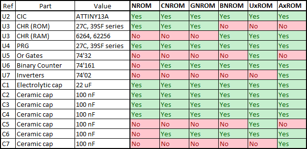
U4 – PRG ROM Chip
Needed for: All game types
Part Number: EPROMs: 27C256, 27C512, 27C010, 27C020, 27C040, 27C080; Flash memory: 39SF010, 39SF020, 39SF040
Function: Holds the Program ROM file. This goes in the socket labelled “PRG”.
How to Program: Check the reproduction article for information (Steps 1, 3, and 4)
U3 – CHR ROM Chip
Needed for: CNROM, GNROM, NROM
Part Number: EPROMs: 27C256, 27C512, 27C010, 27C020, 27C040, 27C080; Flash memory: 39SF010, 39SF020, 39SF040
Function: Holds the Character ROM file (sprite data). This goes in the socket labelled “CHR”.
How to Program: Check the reproduction article for information (Steps 1, 3, and 4)
U3 – CHR RAM Chip
Needed for: AxROM, BNROM, UxROM
Part Number: 6264 series
Function: Holds the ROM’s sprite data. This goes in the socket labelled “CHR”.
U5 – 74’32 – Or Gates
Needed for: UxROM
Part Number: 74HC32, 74HCT32, 74LS32
Function: Used by UxROM to expand ROM data access to higher banks.
U6 – 74’161 – Binary Counter
Needed for: AxROM, BNROM, CNROM, GNROM, UxROM
Part Number: 74HC161, 74HCT161, 74LS161
Function: Used by some board types to expand ROM data access to higher banks.
U7 – 74’02 – Inverters
Needed for: AxROM
Part Number: 74HC02, 74HCT02, 74LS02
Function: Used on some AxROM games to prevent bus conflicts.
U2 – CIC
Needed for: All game types (unless using a top-loader NES, CIC modded NES, or clone console)
Part Number: Original CIC, or programmed ATTiny13 (instructions for programming detailed below)
Function: Completes the region check and allows the game to run on the console.
C1 – Electrolytic Capacitor
Needed for: All game types
Value: ~22 uF, at least 10 V rated
Function: Smooths out supply voltage for the board due to transients on the power supply, prevents quick changes in supply voltage when power is turned off.
C2, C3, C4 – Ceramic Capacitors
Needed for: All game types
Value: ~0.1 uF, at least 10 V rated
Function: Filters out high-frequency noise that can interrupt the EPROMs, RAM, and CIC.
C5 – Ceramic Capacitor
Needed for: UxROM
Value: ~0.1 uF, at least 10 V rated
Function: Filters out high-frequency noise that can interrupt the 74’32.
C6 – Ceramic Capacitor
Needed for: AxROM, BNROM, CNROM, GNROM, UxROM
Value: ~0.1 uF, at least 10 V rated
Function: Filters out high-frequency noise that can interrupt the 74’161.
C7 – Ceramic Capacitor
Needed for: AxROM
Value: ~0.1 uF, at least 10 V rated
Function: Filters out high-frequency noise that can interrupt the 74HC02.
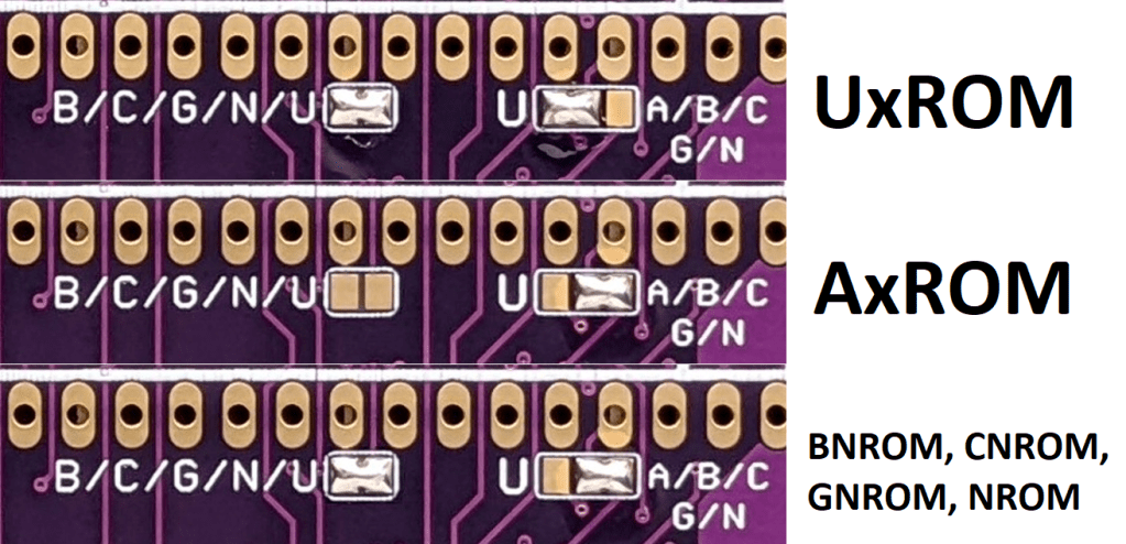
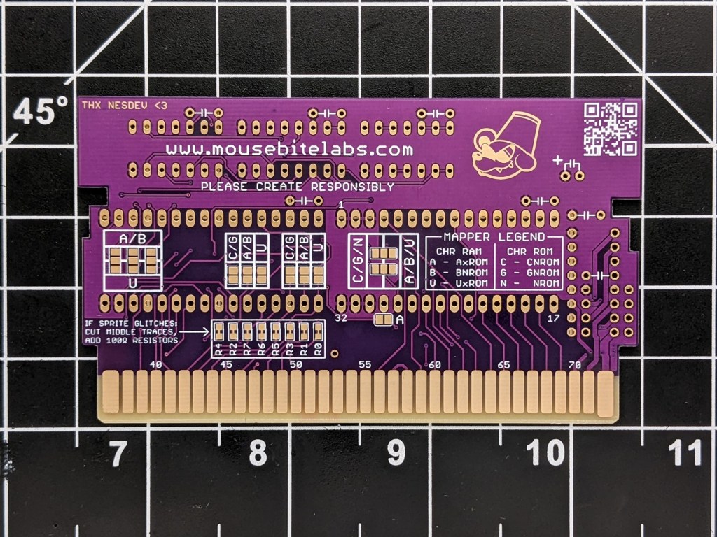
Top Side Solder Pads
The solder pads on this board are for selecting between the six different board types – AxROM, BNROM, CNROM, GNROM, NROM, and UxROM. On the back of the board is a legend for determining which solder pads are needed for which types. Any time you see the single letter of the board type you’re making next to a set of solder pads, that means you need to bridge them.

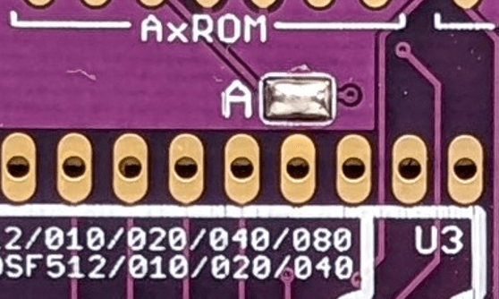
AxROM Pads
Right below the space for the 74’02 is a set of two pads that need to be bridged for AxROM games.
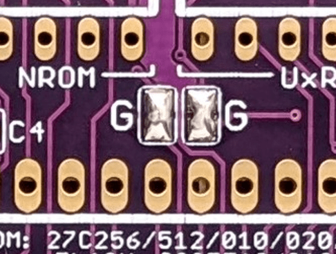
GNROM Pads
Below the 74’161 and 74’32 sockets are two sets of solder pads for GNROM games.
Multi-board Type Pads
On the bottom left are two sets of solder pads. Solder as follows:
H/V Solder Pads
This is to set the mirroring mode for your game. Solder the middle pad to either H (for vertical mirroring) or V (for horizontal mirroring). Yes, I know it’s backwards, and there’s a reason for it if you’re interested. This will vary from game to game. If you make a game, and the graphics are all screwed up, try soldering the other set of pads – this will often fix the problem. The H and V refer to the H and V markings on original NES games, so you can always check pictures on NESCartDB.

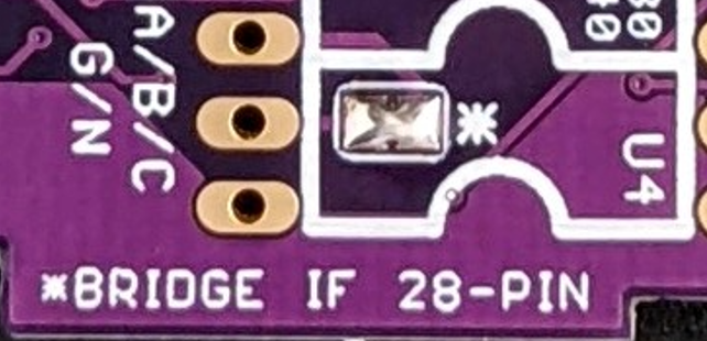
28-Pin PRG Pads
There’s a set of pads above pin 31 of U4 that must be soldered if you use a 28-pin device for the PRG ROM. These pads will be covered if using a 32-pin device: DO NOT solder these if you’re using a 32-pin device!
Back Side Solder Pads
AxROM/BNROM and UxROM Pads
These pads manage connections for the CHR RAM-based board types. If you’re not making any of these three board types, leave these unsoldered.
74’161 Input Solder Pads
These sets of solder pads control the input pins on the 74’161.

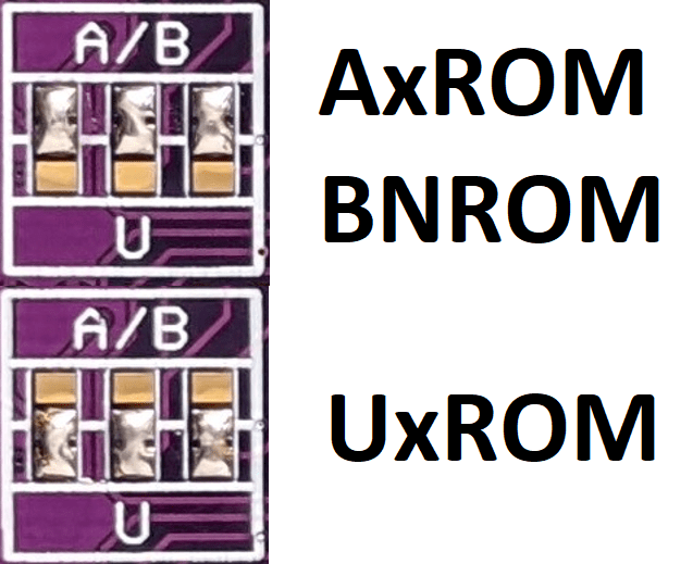
CHR Type Selection Pads
These sets of pads switch between board types that use CHR ROM or RAM.
AxROM Solder Pads
There’s a lone set of AxROM pads underneath the CHR type selection pads. Solder these together if making AxROM games.
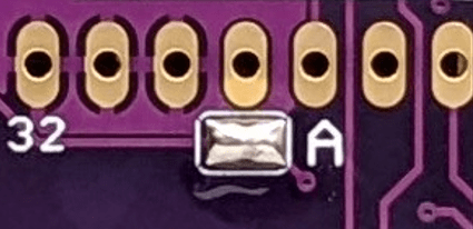
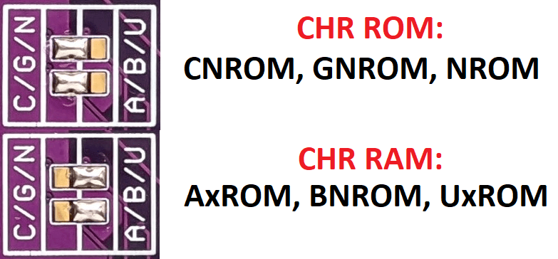
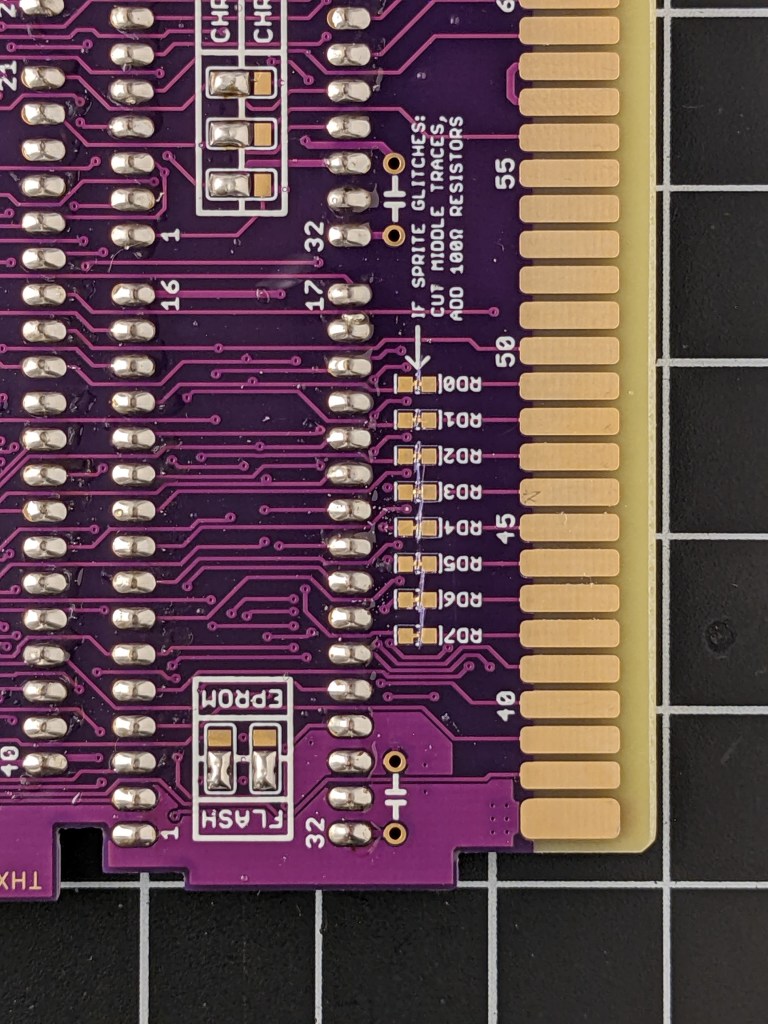
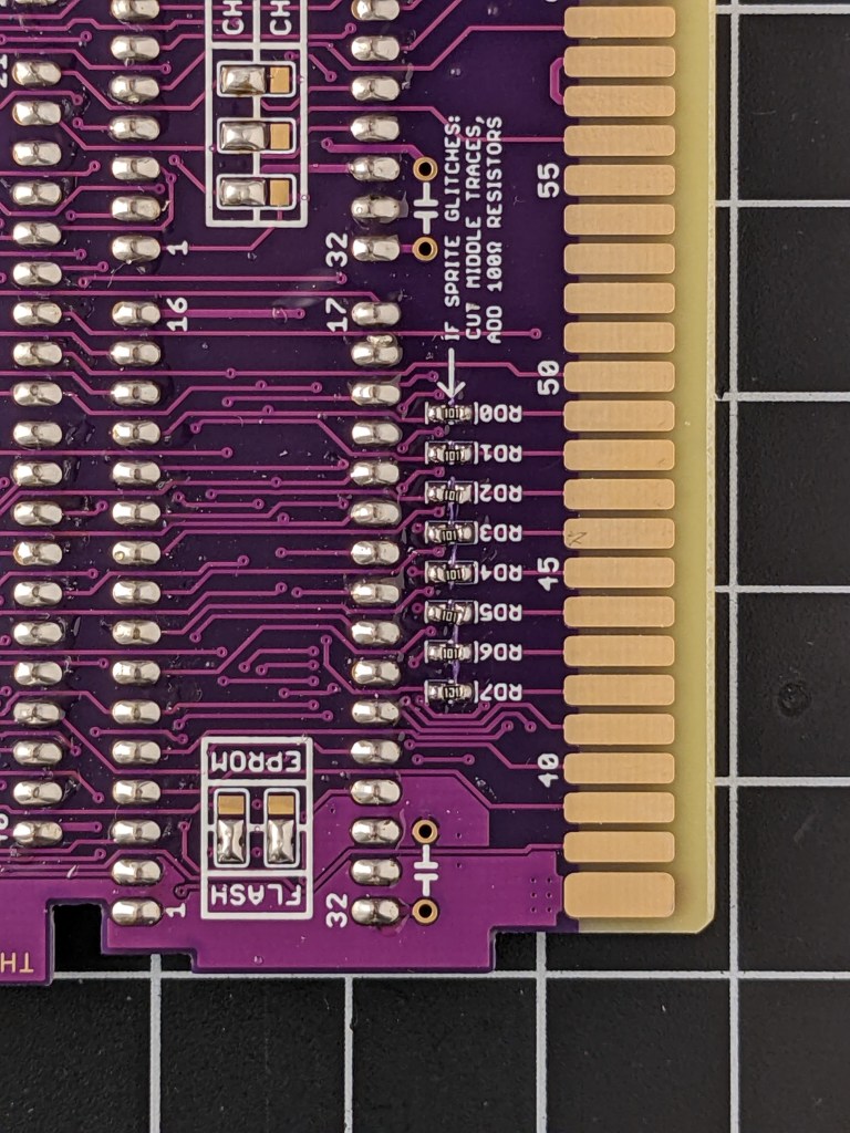
Sprite Glitch Resistors
In rare cases, you might encounter some sprite glitching even if everything is configured properly. This usually only happens when you have things like a Famicom-NES adapter or Game Genie in your system. What sets this aside from other graphical glitches is that it affects the sprites, not the entire screen. So if you’re getting strange palettes, missing backgrounds, or weird tiles, your problem is something else, probably a bad cartridge connector or dirty cartridge edge. What you’ll see if you’re getting this kind of error, known as OAM corruption, looks something like this:
Fixing this error involves adding ~100 ohm resistors in series with the PRG D0 to D7 lines. This can be done by cutting the exposed traces in the middle of RD0 to RD7 with a blade, and soldering resistors in place (surface mount size 0603). Be careful not to cut other parts of the board (or yourself).
(These pictures are from another board, but they are present on the Discrete board as well.)

Again, this is quite rare, so chances are you will be leaving these alone.
Programming the CIC
The CIC clone by krikzz uses the ATtiny13 microcontroller. You need an AVR programmer to properly load the program into the chip. You can use the GQ-4×4 or the TL866.
In order to program the ATtiny13, first load up the chip in the programmer, and load the code found here (I could not find the original file uploaded on kirkzz’s website, but you should still check out his stuff). Make sure you load the .hex file, and load it in as a .hex file. The ASCII code on line 0x380 should read “krikzz was here!” – that’s how you know it loaded correctly.
If you’re using the GQ-4×4, first write the software to the chip, and then set the config bits – so program the chip first. If you’re using the TL866, you can write the code and the config bits at the same time. To set the config bits, hit “CFG” for the GQ-4×4, or the “Config” tab on the right of the screen for the TL866. Then, set the bits like this:

Hit “Write” for the GQ, or program the chip on the TL866, and then you should be good to go!
When you put it into a cartridge and load it on the NES, you will probably need to hit the reset button five to ten times to get it to recognize the region of the NES you’re using. If you happen to use the cart in another region NES, just do this reset process again to reset the region correctly.

[…] Basic NES Reproduction Board Guide […]
LikeLike