Disclaimer: This tutorial is for educational purposes. The instructions and products discussed are for the creation of homemade games only, or for repairing damaged cartridges for personal use, and should not be used for duplicating and distributing games protected by copyright.
I am not responsible for any damage to you or your property – attempt these projects at your own risk! There are a lot of steps, and nearly all of them are crucial to get a working product.
I’ve taken a lot of time to go through and learn all I can about how SNES games work, and I tried my hardest to make a comprehensive and easy-to-follow guide so you can learn a bit about them yourself. Luckily, the SNES cartridge is fairly straightforward once you know the basics; way less complicated than NES cartridges! It is my hope that after reading this tutorial, you’ll have a good understanding on how to make your own SNES cartridges to use in your original SNES hardware. There are some soldering skills required, and it might be frustrating at times dealing with older technology – you’ve been warned!
Table of Contents
Step 1: Gather information on your game
Step 2: Determine the method you will use
Step 3: Choose your board
– Donor cartridge
– Custom PCB
Step 4: Determine which memory chips to use
Step 5: Fix the checksum and remove the header
Step 6: Finalize files for programming
– 27C801
– 27C160
– 27C322
– 29F033
Step 7: Burn your ROM
– 27C801
– 27C160
– 27C322
– 29F033
Step 8: Double check your chips, and prepare the board
Step 9: Install chips on the board
– 27C801 (donor)
– 27C160 (donor)
– 27C322 (donor)
– 29F033 (donor)
– Custom PCB
Step 10: Finish your game
Equipment you will need
You’ll need a few basic things:
1) Programmer. This is what you use to program the chips the game data is stored on. I got mine on eBay for about $50. It’s a TL866 MiniPro programmer. There’s an updated model, the TL866II Plus, and it seems to work just as well. The TL866 has worked flawlessly for me so far, even after many years, and it’s pretty easy to use. There are other more advanced programmers out there, but they run a lot more expensive. I also purchased a GQ-4×4, which is a great higher-level programmer. If you have one of those other programmers, you’ll have to figure out how to use it yourself (though, if you’re reading this and you already own a programmer, you probably know what you’re doing anyway, nerd).

2) EPROMs or EEPROMS. This is what holds your ROM. Functionally, EPROMs and EEPROMs are nearly identical, and either can be used, though I usually stick to EPROMs because of the price and ease of use for the ones available to use with the SNES. EEPROMs, though, can easily be reprogrammed compared to regular EPROMs. There are definitely benefits to either choice.
In this tutorial, I will go over multiple methods of making games using 8 Mbit, 16 Mbit, and 32 Mbit through-hole EPROMs, and also using 32 Mbit surface mount EEPROMs. The parts I most commonly use are the 32 Mbit through-hole EPROMs – the 27C322. Easy to work with, and can hold pretty much any game.

Note that once you’ve programmed an EPROM, you should tape over the window to prevent any data corruption. EEPROMs don’t have a window.
2b) TL866 programming adapters. If you want to use the 27C160 or 27C322, or the TSOP 29F016 or 29F032 on a TSOP adapter board, and you’re using the MiniPro, you’ll benefit from an appropriate programming adapter so that you can program these chips. They are not natively supported by the TL866, but we can easily add the functionality ourselves. Other programmers like the GQ-4X4 can handle the 42-pin 27C series chips without adapters. I make these adapters, and can sell them to you over on my store page, or you can make your own, as I provide schematics for them. I’ll go over which one you might need for your project later on.


3) EPROM eraser. This is for… erasing your EPROMs. You do not need this if you plan on only using the surface mount EEPROMs. I use this thing a lot for trying out different games on my 27C322 EPROMs that I swap in and out of my prototyping boards so I don’t need to solder the chips in to try a game out. But you should get one regardless if you plan on using prototyping boards or not, because you’ll either need to fix something you programmed at some point, or you’ll have to clear the chips you order since they’ve probably got something written on them. Note that you should not leave chips in the eraser for too long – this may permanently damage your parts. I usually leave them in for 20 minutes at a time, and do a blank check to see if they’ve been erased. If not, I throw them in for another 20 minutes. But do not be surprised if you get some bad parts, as these parts are all old stock. They haven’t been manufactured in decades.

4) A board. Probably the most important part! You can use either an existing game that you’ll repurpose (a “donor” board), or a custom designed board. Your game will determine which method is easiest, and which you can even use. I suggest using a custom board when possible, as they are custom-made to make the process as painless as possible, and save the endlessly dwindling supply of original SNES cartridges. I provide custom boards of my own design on my store page if you’re interested. I offer two versions – a “basic” version that can be used for making a single, smaller game; and one that uses the 27C322, capable of making the largest of SNES games, including multicarts! I’ll go into more detail of the differences later on.


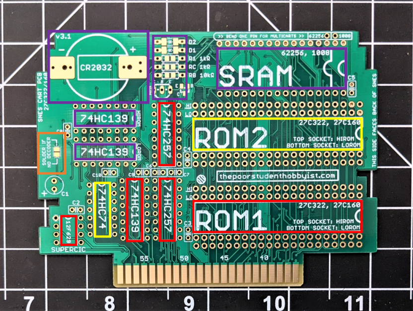
4b) A prototyping board. I have a few boards designated to test EPROMs before I permanently solder the parts into a “clean” board. Basically, I took one of my custom boards and soldered in sockets to allow swapping of the chips without having solder them in place. When I want to make a game, I program my ROMs, put them in the sockets on the prototype board, then use that in my SNES to check and make sure they work. Once I verify the game is running normally, I know that everything is good to go, and I take them out of the sockets to solder them onto a permanent board. I highly recommend doing this, either with one of my custom boards, or with a donor board you convert yourself. It will save many headaches and prevent having to desolder anything – something I really hate doing, and is risky to do if you don’t have experience. It’s very easy to damage boards by desoldering parts. Here’s what a prototyping board looks like compatible with 27C160 or 27C322 EPROMs:

4c) 27C322 or 27C160 EPROM adapters (optional). These will only be applicable if you’re using a donor cartridge. They take a lot of the work out of making your donors work with these EPROMs, as they require rewiring to work on donor cartridges. You could wire the chips up yourself, but it makes the final product look quite messy, and adds a lot of room for error. Plus, I also offer one adapter for games that use the SA-1 processor!


The SA-1 adapter boards are on the left, and the 27C322 adapter boards are on the right. The ‘160 boards look similar to the ‘322s. I also offer a slimmer version of the 27C322 and ‘160 adapter boards that sit directly on top of the ROM socket, but the nice thing about the adapter boards that sit above the board is that you don’t need to remove the original ROM chip!
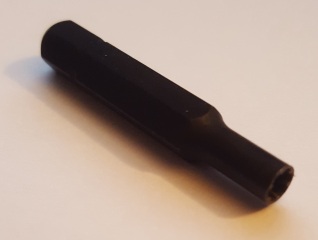
5) Miscellaneous hardware. You’ll need solder, and a soldering iron, at the very least. You might need some wire if you’re using a donor cartridge, I prefer using 28 or 30 gauge kynar wire – flexible, and doesn’t stress the pins on the chips. You’ll also need a special screwdriver for opening SNES games, as they use specific screws. You’re gonna want the 3.8mm “Security Bit” screwdriver. The 4.5mm is used for opening Nintendo consoles and Sega games. Might as well buy both though, they usually come in bundles from what I’ve seen online.
So for making games, if you want my personal recommendation, I’d go with using 27C322 or 27C160 EPROMs, with custom PCBs or a 27C322 or 27C160 adapter board on a donor cartridge. These larger EPROMs really make it easy to put your ROM on a cart, and using them with adapters or custom boards saves you the headache of adding extra wiring.
Items from my store for making SNES games
SNES Cartridge Circuit Board – Basic
SNES Cartridge Circuit Board – Advanced
27C322 adapters for donor cartridges
27C160 adapters for donor cartridges
27C322 adapters for SA-1 donor cartridges
27C160/322 programming adapter for TL866
29F032/33 programming adapter for TL866
Now that you’ve got a good overview, let’s dive in!
Step 1: Gather information on your game
If you’re putting your homebrew game on a cartridge, you probably already know all this stuff about your game, but maybe you’ve found an open source game you want to make. Or you’re dumping a ROM from a game in your library, and you’re putting a copy on a clean new board. The first step you should take is to find out the crucial information of your desired game. To do this, all you need is your ROM file and a few extra pieces of software.
Run your ROM in an emulator
It’s important to run your ROM in an emulator to determine it’s the exact game you want to make, especially if you patched it. I’d recommend higan for emulation, as it tries to emulate the original SNES hardware as closely as possible, so you’re more likely to catch any errors. Read the User Guide on how to use it – it’s actually a helpful document!
So make sure that the game is the exact version that you want to use, and that it can run for a few minutes without freezing. Nothing worse than finishing a game up and finding out after five minutes at a specific screen there’s a glitch you missed.
uCon64
Once you’ve verified that your ROM is correct, you’ll need to download the most important program we will use, called uCon64. This is a command line utility that will give you all the information you ever wanted to know about your ROM. Using it is a bit tricky, though, so I’ll go through what you need to do here.
(I recommend making a folder where you can put all of your work materials to make it easier to navigate.)
Download and unzip uCon64. Now, open Command Prompt. Change the directory to the folder where uCon64 is located by using the cd command (it’s located on my D drive, shown below). If the cd command doesn’t work, try adding /d after it (for folders in different drives).
cd [path to folder] OR cd /d [path to folder]
An alternate method in Windows is to just go to the folder, and type “cmd” in the address bar and hit enter. It will automatically open up Command Prompt with the directory set to the folder you’re in. Handy!
Now, separately navigate to the place where your ROM is located. Hold the shift key and right click on the ROM, and click “Copy as path.” Go back to your Command Prompt screen and enter:
ucon64 [path to ROM]
Use CTRL+V to paste the path. Now hit enter, and you’ll get a lot of information in front of you.
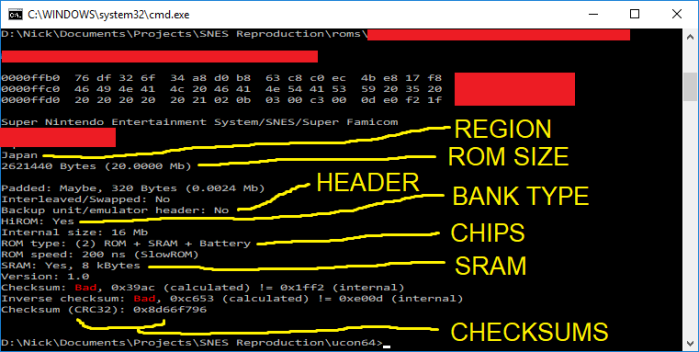
Let’s take some time to go over what each of these categories are.
Bank Type
There are two main types of “banks” known as HiROM and LoROM. In the command window, HiROM games will display as “HiROM: Yes” and LoROM games will display as “HiROM: No”. Pretty self explanatory.
Note that the ExHiROM format will show up as HiROM. As far as I know, there is only ONE true ExHiROM game – Tales of Phantasia. Nearly every other “ExHiROM” game, that is, a game that uses the HiROM mapping type with a ROM size larger than 32 Mbit, will not work on a traditional ExHiROM board. (They will however, work on my custom SNES Advanced boards.)
SRAM
Some games use SRAM, some do not. If yours uses SRAM, you should try to provide it with the exact amount it requires. The reason being is that some games check to see if the amount of SRAM available equals a specific amount. Worst case, give it more SRAM than it needs, and if it doesn’t work, you can always make some adjustments to the larger chip to make it look like smaller amounts of SRAM.
ROM Type (Chips)
This lists any specialty chips the game uses. This doesn’t include the chips that are default on all games, like the CIC region chip or the ROM chips. For example, Star Fox 2 uses the Super FX chip.
Another common thing that many games use are batteries. I’d recommend buying a handful of new batteries with battery holders if your game uses one, even if you’re converting an older cartridge to a different game. It’s been about 30 years since many of these games came out – their batteries are probably almost dead, if they aren’t already. I recommend getting the ones that come pre-tabbed. The original batteries are spot-welded to the holders so they don’t move – replacing just the batteries without removing the mountings is tricky and not worth the time (and potentially dangerous).
Note that you will generally get a longer battery life if you buy name brand batteries. Generic ones from random eBay sellers will work too, but they usually won’t be holding the expected mAh rating when you get them.

Region
You need to make sure the ROM you’re using is formatted for the correct region – PAL or NTSC – otherwise, they won’t run well (or at all) on your SNES/Super Famicom. Look up where you live and if it’s in the PAL region or the NTSC region if you’re unsure. Converting a game from one region to another is difficult or impossible, and it isn’t as easy as disabling the region lockout chip (CIC chip). Countries in the PAL region run on 50 Hz power, where countries in the NTSC region runs on 60 Hz power, and this causes some games to run faster or skip frames if you use them in the wrong region. Analog video encoding is a tricky thing.
Do not ask me how to change a game’s region.
ROM Size
This is how large your game is, obviously. The size only comes into play when you’re deciding which chips to use to program your game, because most cartridge boards are capable of handling pretty much any size game you can make.
Speed
This corresponds to the data access delay times of the ROM. You can pretty much ignore this, as most EPROMs and EEPROMs available anymore will be fast enough for both types of games. If you’re worried, make sure the datasheet of your chip specifies AT LEAST 120 ns access time (120 ns or less). I’ve never run into one that was slower than this though. If you’re curious about the differences between SlowROM and FastROM, check out my detailed write-up about the SNES cartridge inner workings.
Knowing all this information now, you should note the region, ROM size (specifically the number shown in Mb), SRAM size, bank type, and chips that this screen shows. With this information, we can determine exactly how we want to make this game.
Step 2: Determine the method you will use
There are two ways you can make a cartridge. You can use a donor – taking an older game (hopefully a cheap, very common one) and removing the ROMs and replacing them with your own. The other option is to use a brand new board to make the game. There are pros and cons to each. But before we get into the nitty gritty details, your decision might already be made for you. Here are two situations that will make your decision for you:
- If the “ROM Type” line (chips) in ucon64 says anything EXCEPT a combination of ROM, SRAM, and/or Battery, you must use a donor cartridge. This means games that use, for example, the SA-1 chip cannot be made with a custom board, outside of a flash cartridge. Some of these games with specialty chips will have easy through-hole parts to replace, but most will use surface mount parts that makes them trickier to replace. I do offer adapters to make SA-1 games easier to make, but otherwise, I will not be covering other board types that use surface mount chips, like SuperFX for example.
- If your ROM size is larger than 32 Mbit, you should probably use a custom PCB. You CAN use a donor, but the game will require more complex rewiring, and it’s just probably easier to use one of my custom PCBs to handle it. At any rate, I won’t be going over how to use donors for these games in this tutorial.
If your game uses “normal” chips and is 32 Mbit or smaller, then you’ve got a decision to make! Let’s go over the differences between donor cartridges and custom PCBs.
Using a donor cartridge
Using a donor cartridge involves removing or disabling the ROMs on the existing board and replacing them with chips you program yourself.
Pros to using a donor cartridge:
- You won’t have to supply your own plastic case.
- You can pick a game that comes with the necessary components, like RAM, so you don’t have to buy them yourself.
- Because of these two reasons, the price can be cheaper than using a custom PCB.
Cons to using a donor cartridge:
- You might have to remove or cut pins on the existing ROM (and possibly the battery), which can be a huge pain, and if done without caution, can easily damage the board.
- The assembly might look messy with a lot of extra wires, depending on the chips you use to program the game on.
- Because you’re modifying decades-old hardware, and in some cases you’re trying to make it do things it wasn’t originally designed to do, you might have a higher failure rate.
- You’re destroying an otherwise good SNES game. If you’re a proponent of video game preservation, this might not appeal to you. Though, you’ll probably be destroying a crappy sports game, and I can’t tell you what to do with your money, so use your best judgement!
- Removing stickers from cartridges is my least favorite part of the entire process. It seriously sucks. I’m probably doing it wrong, but still.
Using a custom PCB
There are a bunch of different sellers out there that will sell you brand new PC boards that you can use in your SNES as cartridges (including yours truly).
Pros to using a custom PCB:
- The final build will look a lot cleaner, since you won’t need to rewire anything. (And you might even get it in a nice swanky color)
- You don’t have to spend time figuring out a compatible game to use as a donor cartridge.
- It is much easier to make a fully-functional test board with sockets on a custom PCB than on a donor.
- You’ll be supporting the retro video gaming community! And you won’t be destroying a perfectly good soon-to-be-endangered SNES cartridge in the process!
Cons to using a custom PCB:
- You need to buy the extra components (such as SRAM, capacitors, and a lockout chip), and the plastic case, making the final cost most likely a bit more expensive.
- Like I said before, you will only be able to make games that do not use specialty chips.
- Some of the cheap boards you find online might be a poorer quality product. Though there are plenty of high-quality sellers out there!
Now that you have a better idea of how you want to make your game, let’s get the proper board. Skip ahead if you’re using a custom-made board.
Step 3a: Choose your board (donor cartridge)
First, you’ll need to open up this Excel document I made. This document has information on most available ROMs for SNES/Super Famicom, including foreign games, and even some ROM hacks. You can download it and open in Excel, or Office Libre, or just use Google Sheets to organize the data. I got the information for this spreadsheet from the SNES ROM Header Database. I trimmed some of the fat off of the list, like games that have weird amounts of SRAM or customized things that didn’t filter well in the Excel document.
Go back to your notes on the bank type, SRAM amount, and extra chips that your game uses. You should filter the columns for those characteristics to find a good, cheap donor. Note that instead of filtering the region column, you should filter the video column instead depending on if you’re in the NTSC or the PAL region.
To find a donor cartridge, go to each of the filtered column drop down menus. Deselect each value that your game DOESN’T have in the Bank, SRAM, Chips, and Video columns. I also sorted the list by the game column from A to Z to group all common games together – makes it easier to sort through the titles. You should now have a list of compatible games. This screenshot shows all the HiROM games with 64 Kbit of SRAM in the NTSC region.

Note that you should be sure that the game you pick for a donor isn’t a hack or mod itself, because that won’t be the actual cartridge you can buy! Make sure the game you pick has an entry in the sheet that either has [!] or no additional information past a version number and region code (NOT translation code). There are a few games that, for example, might use HiROM instead of LoROM if you have a certain translation or mod. You will be buying an original game so you MUST make sure the original is on your donor list!
Now, if you want, you can check out your selected donor cartridge over on SNES Central. Note that the original ROM socket can come in a 32-pin or a 36-pin variety. Unless you’re making a game that’s 8 Mbit or smaller, you’ll have a MUCH easier time with the process if you get a board that has a 36-pin socket (and I won’t be going over how to use a 32-pin board for games larger than 8 Mbit). So in general, stick with 36-pin boards for games larger than 8 Mbit. Also, some games come with two or three ROM chips on them – I won’t be covering those types of boards in this tutorial either. There is way too much variation. Please do not ask me how to use them, because I probably won’t be able to help easily without having the cartridge in front of me 🙂
Another important note is that some games that use specialty chips will sometimes use surface mount parts on their boards instead of through-hole parts. This makes using them a lot trickier. It’s still possible, but they’re not the easiest to work with. Other than the SA-1 games, I will not be covering those types of games in this tutorial.
Once you have your donor cartridge, you should DEFINITELY check to see if it works as is in your SNES. You don’t want to get to the end of the process only to find the game you bought is broken (which has happened to me). You might have to clean the cartridge edge to get it to work. Now, let’s decide the next most important aspect of your game – what chips to load your ROM on. Head to Step 4.
Step 3b: Choose your board (custom PCB)
I currently offer my own SNES cartridge boards – a basic version and an advanced version. Here’s a quick list of the features of each:
SNES Basic Board
- Holds one game on a 27C801 (8 Mbit), 27C160 (16 Mbit), or 29F032/033 (32 Mbit, with adapter board).
- Has a socket for original SNES ROM chips, so you can transfer the original ROM to a new board.
- Can use the original CIC, or the SuperCIC clone.
- Supports games that save, with SRAM sizes up to 1024 Kbit.
SNES Advanced Board
- Uses the 27C160 (16 Mbit) or 27C322 (32 Mbit) EPROMs.
- Can use two 27C322 EPROMs, or one 27C322 and one 27C160, to make games up to ~64 Mbit large, commonly referred to as ExHiROM and ExLoROM (this includes ROM hacks and translations)
- Can use two 27C160 or 27C322 EPROMs to make a multicart for two games, switched by pressing the reset button on the console.
- Supports games that save, with SRAM sizes up to 1024 Kbit (or separate saves for the games if making a multicart, up to 512 Kbit each)
The advanced board should cover any SNES game that doesn’t use specialty chips, or has some kind of unique mapping scheme (like the Star Ocean hack), but the basic board is a great option for games 16 Mbit or smaller, or for moving parts from an old game to a brand new board.


If you elect to use someone else’s board, that’s fine, you’ll just have to rely on them for instructions where it isn’t clear what to do. I will provide (hopefully) easy-to-follow instructions later on for my own boards – it might look daunting, but trust me, it’s easier once you get into it!
Now let’s decide the next most important aspect of your game – what chips to load your ROM on!
Step 4: Determine which memory chips to use
There are four widely used memory chips to load your ROM into that I will go over in this section. Which you choose will be determined by a few factors, most notably your ROM size, and if using a custom PCB, the compatibility of your board.
- 27C801 – a through-hole 8 Mbit EPROM
- 27C160 – a through-hole 16 Mbit EPROM
- 27C322 – a through-hole 32 Mbit EPROM
- 29F033 – a surface mount 32 Mbit EEPROM
There are plenty of alternatives with the same pinouts that will work just as well as these four (such as the M27C080 for the 27C801, or the 29F032 for the 29F033). I’ll be using these numbers listed above when referencing these chips to make the tutorial easier to read.
There are a ton of different ways to make games with these chips. I’m only going to cover the most common and easiest to use cases here. For that reason I recommend you getting a chip that’s either as big or bigger than the ROM you want to put on a cartridge.
As far as my personal preference goes, I’ve been using 27C322’s (on my own boards) for most of my games for a while now. I recently got some 27C160s to use with my basic boards as well, for any simpler games I want to make. I stay away from 29F033’s because of the annoyance in soldering them, but if you can get them mounted properly they are quite handy. I have one that I use for testing.
Checking your ROM in the SNES ROM Utility
Before you continue, you should download the SNES ROM Utility program and load up your ROM. We’re going to be using this program pretty heavily. Most games should load up fine, but you might get some errors. In the cases where your ROM doesn’t load, you’ll have to do some research or possibly use another version of your ROM.
So now, I’ll give a rundown of the different chips you can use for your games, and some pictures as examples. (Note that the window on top of the EPROMs should be taped over to prevent data loss – in some of these pictures I neglected to show that. Oops.)
8 Mbit EPROMs
If your game is only 8 Mbit large, you can very easily and cleanly use just one of these EPROMs, like the 27C801. There are only two pins you’ll need to reroute on donor cartridges. These are getting a bit expensive from what I’ve seen, but they make for very clean installs of smaller games on donor cartridges, and even cleaner installs on my custom boards. Here are a few pictures.


16 Mbit EPROMs
16 Mbit EPROMs, like the 27C160, I’ve found to run cheaper than the 801’s. There are only two (quite minor and avoidable) downsides to using these chips. For one, it’s going to look ugly, as it requires a bunch of wires similar to the picture above – unless you use an adapter board like this one, or this other version that’s extended above the donor PCB and requires no desoldering. Secondly, you’ll need a special programming adapter to program these in the MiniPro programmer.
Here’s a small gallery of examples of boards using 27C160s.


32 Mbit EPROMs
32 Mbit EPROMs are the largest through-hole parallel data EPROMs available. Luckily, most SNES games are 32 Mbit or smaller. I use the 27C322. Like the 27C160’s, they will look ugly if you’re using a donor board without an adapter – it has 42 pins, so you have to wire many of the pins individually to the socket correctly. In addition, you’ll need to provide two multiplexer ICs to change the 16-bit data bus of the 27C322 into an 8-bit data bus of the standard SNES cartridge. This is so ugly, in fact, I have never made one without an adapter board. Coincidentally, like the 27C160s, in order to remove all the manual wiring, I do sell these adapter boards that do the wiring for you! They’re extremely handy, and I don’t think I’d recommend using these chips on a donor cartridge without them. I also provide an extended one that’s a bit easier to use and doesn’t require any desoldering.
Also note that, like the 27C160’s, you’ll need a programming adapter to program them on the MiniPro which I can provide you with.
Here’s a gallery of pictures of different ways you can make a game with the 27C322: one with a slim adapter board, one extended adapter board, and one on a custom board (the example picture with my custom board specifically shows an ExHiROM game, which uses two 27C322s).


An important note – if you’re planning on making an SA-1 game with an SA-1 donor board, I recommend using one of these SA-1 EPROM adapter boards. This allows you to use a 27C322 on the board instead of the original surface mount ROM chip. Here’s what a game looks like completed.

32 Mbit EEPROMs
As for the 32 Mbit EEPROMs, I use 29F033 chips. These are surface mount parts, so an extra breakout board is necessary to program and insert into the SNES PCB. You can get these boards from various places, like buyicnow. Sometimes they come pre-mounted and tested, so that’s pretty nice.
The upside to using the 29F033 is that everything will look a lot cleaner and the process will be much quicker (once it’s mounted to a board), as you won’t need to do any rewiring. The downside besides the price is, well, it’s a lot harder to solder surface mount parts than it is through hole. If you don’t have any experience soldering surface mount, and you buy them separate from the board, this might be a harder option for you.

The type of pins you’re gonna be soldering are circled in red in that picture above. So my advice, only if you are confident in your ability to solder extremely small pins and are willing to spend a bit of extra money to make your life marginally easier, is to only use the surface mount 32 Mbit EEPROMs with breakout board only for any game larger than 16 Mbits. But again – this is a difficult process, especially if you’re new to soldering. And you might kill a few of these chips if you don’t solder them properly by keeping heat on the pins for too long. If you haven’t had a lot of experience in soldering such tiny pins, or aren’t willing to potentially waste a bit of money in damaged chips, I would recommend just using the through-hole EPROMs.
But if you feel so bold, my tips if you’re wanting to try to solder this surface mount chip: get yourself flux. Flux will make your solder flow much better, and is essential if you want to attempt this (trust me… I tried to do it without it). Just spread it on all the pins. And maybe invest in an adjustable magnifying glass stand. Make sure you have really good lighting. And lay off the coffee… you need steady hands for this one. But if you’re able to, you’ll get a pretty compact board.


Note that if you plan on going this route, and you want to use the TL866 programmer, you’ll need to either buy my adapter, or make your own to route the wires on the breakout board to the programmer. Or, use a programming adapter for the small TSOP packages to program them before soldering them to the adapter board.
I do not recommend using these TSOP chips for donor boards that have 32-pin sockets. If you do, make sure your game is 8 Mbit or smaller.
Figured out which chips and what kind of board you want to use? Great! Let’s get your ROM file ready to program.
Step 5: Fix the checksum and remove the header
Now you’ve chosen what kind of board you’re going to use and your chips, let’s take a look at that command window again.
Let’s start with the checksum. If the checksum areas say “OK” and are green, you’re good to go! Skip over this section.
Fixing the checksum – IpsAndSum
In the picture above, my checksums are bad (this usually only happens when games are translated or modded). If your checksums are bad, then you need to run your game through a program called IpsAndSum. This program is a bit glitchy, but it’s pretty easy to figure out.

First, you’ll need to go to File > Open, and choose your ROM. Sometimes the numbers will change in the fields on the screen, sometimes they’ll stay at 0000. Like I said, glitchy. Either way, go back to File > Repair SNES CheckSum, and the fields should change. Click “Yes” to repair. Then, make sure you go to File > Save to save your fixed ROM.
You should run the ROM through uCon64 once again to make sure the checksums got fixed, and that you remembered to hit File > Save (this happens more often than you’d think).

At this point, if your checksums are still bad, you might have to try another ROM if possible, or try going through the steps again in case you missed something along the way. If you still can’t get the checksum OK, then the ROM still might run ok in the console, but proceed at your own peril. Maybe you can try it out on a prototyping board like I mentioned earlier to avoid having to solder anything down onto the board.
Removing the header and finalizing the files – SNES ROM Utility
Here’s what the screen looks like when you load a ROM into it.

You’ll see some of the information of the ROM here that you already saw in uCon64. In the next step, we’ll use SNES ROM Utility to finalize the chips for programming.
Step 6a: Finalize files for programming (27C801)
Step 6b: Finalize files for programming (27C160)
Step 6c: Finalize files for programming (27C322)
Step 6d: Finalize files for programming (29F033)
Step 6: Finalize files for programming
This process will look a bit different depending on the chip you’re using, so I’ll split it into sections for each chip.
Finalizing for 27C801
If you’re using the 8 Mbit EPROMs, there’s really only one option we’ll need to pick under the task list – SwapBin. This command does everything – it removes the header for us and performs a process that switches the data in the ROM around to make our modifications to the cartridge a bit easier.
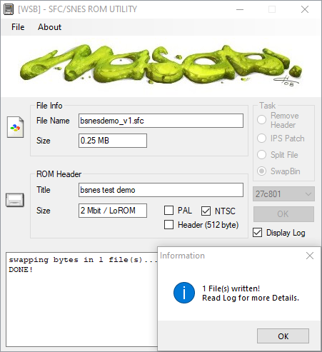
Check the SwapBin button, choose 27C801 on the drop down menu and click OK. You’ll get this notification, and if you look in the folder where your ROM was located, you should see a new file created.
Note that if you load up a game larger than 8 Mbits, it’ll split the ROM into multiple files. You can do this like I mentioned, but you’ll need to wire up some extra hardware and chips, but really, it’s such a hassle so I don’t recommend doing it.
Explanation of SwapBin
This is really only if you’re curious why we do this step. If you’re not, carry on to Step 7a.
Compare the pinouts between the SNES ROM socket and the 27C801 EPROM we are going to use. Like the NES, the SNES games use a proprietary pinout for the ROMs, so we need to do some rewiring.

However, many of these pins line up to other data pins. For example, pin 1 on the 27C801 is A19, but on the SNES PCB, this pin is A17. So, instead of having to rewire A17 and A19 to different places, we can use software to digitally swap these two address pins by modifying the ROM. That way, we can emulate a different pinout for the EPROM.
SNES ROM Utility switches A19 with A17 and A16 with A18. Now there’s only two extra wires we’ll have to solder for this EPROM to swap /OE and A16 (since /OE can’t be changed).
Now that you know why we’re doing this SwapBin business, skip ahead to Step 7a.
Finalizing for 27C160
If you have a programmer that can natively program a 42-pin EPROM, then all you have to do is remove the header, if you have one (remember, uCon64 wells you if you have a header). Easy! Load up your ROM in the utility and select “Remove Header.” Then skip ahead to Step 7b.
If you have a TL866, you’ll need the 27C322/160 programming adapter. All you need to do is load your ROM into the utility, and check the “Split File” button. Then, on the drop down menu, pick the 512 kB option (512 kilobytes = 4 megabits). Luckily, if the ROM has a header, the Split File option will automatically remove it for us when it splits!

Since this ROM is 16 Mbit, it will split into 4 separate files. Your folder should now contain multiple files that are 512 KB large. I’ll explain in Step 7b why we need these chunks, and how we’ll program these chunks individually into our EPROM.
Finalizing for 27C322
If you have a programmer that can natively program a 42-pin EPROM, and your game is 32 Mbit or less, then all you have to do is remove the header, if you have one (remember, uCon64 tells you if you have a header). Load up your ROM in the utility and select “Remove Header.” Easy! Then, skip ahead to Step 7c.
As I said, if you have a TL866, you’ll need the 27C322/160 programming adapter. All you need to do is load your ROM into the utility, and check the “Split File” button. Then, on the drop down menu, pick “512 kB”(512 kilobytes = 4 megabits). Luckily, if the ROM has a header, the Split File option will automatically remove it for us when it splits!

Since this ROM is 32 Mbit, it will split into 8 separate files. Your folder should now contain multiple files that are 512 KB large. I’ll explain in Step 7c why we need these chunks, and how to program them onto your EPROM.
Finalizing for 29F033
This step is super easy if you’re only using one 29F033 EEPROM. If when you load your game into the Utility, and it shows that it has a header, just check the “Remove Header” option and click OK. If you don’t have a header, and your game is 32 Mbit or less, then you’re already done! Go to Step 7d.
Step 7: Program your ROM
Like the previous step, I’ll split this one into sections based on the chip you’re using. If you’ve got a different programmer than the TL866 or TL866II, then this step won’t really be applicable to you. Go ahead and program your chips and skip to Step 8.
Programming on a 27C801
As usual, make sure you blank check your EPROMs before you program them and clear them if necessary. I think you’re smart enough to figure out how to program your EPROMs with your programmer, especially if its the TL866 – it’s super easy to figure out. I believe in you! You’ll also want to tape over the little window so the games don’t get randomly corrupted sitting out on your desk.
Now go ahead and skip ahead to Step 8, where we’ll get our board ready.
Programming on a 27C160
Burning your 16 Mbit EPROM, as I mentioned before, requires you to trick the programmer. What we’re going to do is program the 4 Mbit chunks we just made, and manually change the A18 and A19 pins. You can do this yourself by making your own adapter, or you can buy mine.
As I said earlier, the TL866 doesn’t support the 160. However, it does support other, smaller 16-bit EPROMs, like the 27C4096. The 4096 is a 16-bit EPROM, however, it can only store 4 Mbit of data. That’s why we split the ROM into 4 Mbit chunks. We’re going to trick the TL866 into thinking we’re programming the 27C4096, when in reality, we’re going to be programming our 27C160 and manually switching the top two bits, A18 and A19, between 0 and 1. This will give us 4 sections of 4 Mbit chunks, for a total of 16 Mbits. A18 and A19 represent what’s known as “banks” of data.
Here’s what my adapter board looks like:

As you can use this adapter for the 27C322’s as well, make sure the switch is in the 27C160 position. If you’re instead interested in making your own adapter, I provide the schematic and details of operation over on my documentation page.
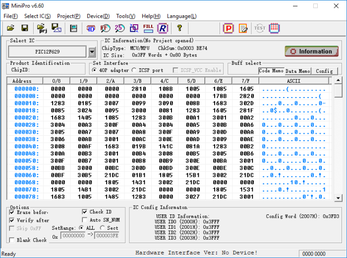
So now, you can get to programming. Load up the 27C4096 chip on the TL866 software, and load up the first file from your ROM (ending in _01). Change the VPP to 12.5 V, as this is dictated for programming voltage in the datasheet for the 160. Then, uncheck the “Check ID” option. If you have a TL866II, then you’ll also have to uncheck “Pin Detect”. Your window should look similar to this:

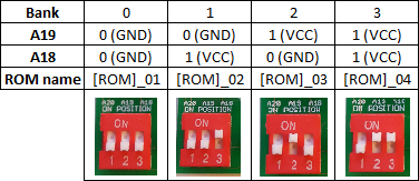
Here’s a table of how data is programmed into the EPROM. If A18 or A19 is a “0”, that means tie it to GND, or if you’re using the adapter, put the switch in the “OFF” position. If it’s a “1”, that means tie it to VCC, or if you’re using the adapter, put the switch in the “ON” position. Program the 4 Mbit chunks that were made by SNES ROM Utility in sequential order in the banks.
If you get an error while programming with the MiniPro – make sure your chips are in the correct orientation, each bank is blank, and that you’ve selected a 27C4096 EPROM from the Select IC list! Also, make sure you’ve got the switch on the adapter board on the 160 option (if you’re using the combination adapter board). Now, tape over the window on top of the EPROM to prevent data decay, and carry on to Step 8.
Programming on a 27C322
Burning your 32 Mbit EPROMs, as I mentioned before, requires you to trick the programmer. What we’re going to do is program the 4 Mbit chunks we just made, and manually change the A18, A19, and A20 pins. You can do this yourself by making your own adapter, or you can buy mine.
The 27C322 is programmed through the data pins Q0 – Q15. This is a bit different than the 8 Mbit EPROMs and the 32 Mbit EEPROMs, which only use 8 data pins (Q0 – Q7). We’ll have to add a bit of extra circuitry to use them in the SNES cartridge, but for now, we just need to know that we need to program our ROMs using all 16 bits.
As I said earlier, the TL866 doesn’t support the 322. However, it does support other, smaller 16-bit EPROMs, like the 27C4096. The 4096 is a 16-bit EPROM, however, it can only store 4 Mbit of data. That’s why we split the ROM into 4 Mbit chunks earlier. So we’re going to trick the TL866 into thinking we’re programming the 27C4096, when in reality, we’re going to be programming our 27C322 and manually switching the top three bits – A18, A19 and A20 – between 0 and 1. This will give us 8 sections of 4 Mbit chunks, for a total of 32 Mbits. A18, A19, and A20 represent what’s known as “banks” of data.
Here’s what my adapter board looks like:

As you can use this adapter for the 27C160’s as well, make sure the switch is in the 27C322 position (shown above). If you’re instead interested in making your own adapter, I provide the schematic and details of operation over on my documentation page.
So now, you can get to programming. Load up the 27C4096 chip on the TL866 software, and load up the first file from your ROM (ending in _01). Change the VPP to 12.5 V, as this is dictated for programming voltage in the datasheet for the 322. Then, uncheck the “Check ID” option. If you have a TL866II, then you’ll also have to uncheck “Pin Detect”. Your window should look similar to this:
Here’s a table of how data is programmed into the EPROM. If A18, A19, or A20 is a “0”, that means tie it to GND, or if you’re using the adapter, put the switch in the “OFF” position. If it’s a “1”, that means tie it to VCC, or if you’re using the adapter, put the switch in the “ON” position. Program the 4 Mbit chunks that were made by SNES ROM Utility in sequential order in the banks.

If you get an error while programming with the MiniPro – make sure your chips are in the correct orientation, each bank is blank, and that you’ve selected a 27C4096 EPROM from the Select IC list! Also, make sure you’ve got the switch on the adapter board on the 322 option.
After you program your eight chunks, tape over the window on top of the EPROM to prevent data decay, and carry on to Step 8.
Programming on a 29F033
If you’re using the surface mount EEPROM with the adapter board I mentioned earlier, you’ll need to do a bit of extra wiring to accommodate for the breakout board. Nothing extreme! The good news is your board will look much cleaner in the end compared to the boards you make using the DIP package EPROMs from above.
On the DIP36-TSOP40 adapter board, you might have noticed a few extra pads on the top of the board. (The board I’m using for this example is from buyicnow.com, it’s version III. Other versions should work fine, but you’ll need to check for differences).

The pads we are going to worry about (R1 and R3) connect to the RESET and the /WE pins. These pins aren’t directly routed to any of the pins for the DIP package, as the SNES ROMs don’t use these pins. But, in order to program our 29F033, we need to do something about these pins. R1 connects the RESET pin to Vcc. This will ensure the chip is always on, which is obviously what we want. R3 connects the /WE (write enable) pin to pin 36 on the DIP package. This will be used by our programmer to enable writing the code to the chip, but when the adapter board is connected to the SNES PCB, this pin will be pulled to Vcc during operation, ensuring the chip never re-enters Write mode.
We need to short both R1 and R3. The easiest way to short these pads is to strip back a wire that covers both pins, solder both pads onto the wire, and then clip the remaining piece of wire. If you want, you could also spread some flux on the pads and short them that way, but be careful not to heat up the pads too much, because you don’t want them to fall off (which is something I’ve done…)

You can completely ignore SJ1 and R2. Not necessary for our project.
Normally, to program surface mount chips, you usually need to get some sort of adapter for your programmer. They look like this:

All you do is drop your surface mount chip in the little box and make sure the pins are lined up, and you can program it like a normal through-hole chip. Now, these things are stupid simple. They’re literally just traces that reroute the tiny little pins on the surface mount package to larger, DIP-sized pins that your programmer accepts. I get that it’s a niche product, but still. I don’t want to drop extra cash on one of these things. If you think you’ll be programming a ton of these little guys, you can go ahead and pick one up, but I don’t use EEPROMs all that much outside of these projects.
With our DIP36-TSOP40 adapter board, we kind of have an adapter already. It’s just attached to a single chip. The problem is, this adapter board we have adapts the pinout to the SNES Mask ROM pinout, which is (unsurprisingly) NOT the same pinout that our programmer uses. So we have to make an adapter for our adapter.

That was hard to type. Anyway, here’s what my adapter adapter looks like.

If you want to learn how to make your own instead, head over to my documentation page. Once you have your adapter ready, place your chips in and blank check, clear if you need to, and program your game.
Step 8: Double check your chips, and prepare the board
You should definitely check off all these boxes before you go any further. Once you’ve soldered your chips in, getting them out is a risky and very frustrating process! I’ve killed at least a few boards because I ripped the pads off from desoldering and soldering so much. Maybe you should make a prototype board to try them out before soldering? Anyway, ask yourself the following:
- If using a donor board, is it compatible with my desired game (bank type, region, etc)?
- Did the ROM run on an emulator correctly?
- Did I remove the header from the ROM file?
- Are there any broken traces on the board, specifically beneath where I will be placing the chips?
- Is there any extra solder anywhere on the board that might be making unwanted connections?
- Did I run ucon64 a final time to absolutely make sure the checksums are correct?
- If I split the ROM into multiple chunks for the 160 or 322, did I program the banks in the correct order?
Making sure you’ve done these things will save you a lot of time and a lot of headaches, so make absolutely sure you’ve followed them.
Now, if you’re using a custom PCB, you can skip ahead all the way to Step 9e. As for you donor people, have you gotten all your materials from eBay in the time it took you to read through this wall of text yet?
SNES games can have a lot of different chips, but you’ll only need to worry about one at this point – the original ROM chips. You’ll want to keep all the other chips exactly where they are. Some games have two or three ROMs, but this is uncommon – I won’t be covering those cases in this tutorial, because if I did, this tutorial would be at least twice as long! The ROMs are denoted on the PCB in some way, it’ll say “MASK ROM” or some variant of it. If your game doesn’t have any RAM or specialty chips, the ROMs will be the only large chips on your board.

You can see above that U1 is labelled as MASK ROM, which is the chip we need to remove. U2 is the SRAM, which we want to keep in the board.
Note that if you’re using one of my extended adapter boards, you don’t need to remove the original ROM! Very handy! Go ahead and skip ahead a few paragraphs.
Removing the mask ROM from their boards is kind of difficult, but you have a few options. The easiest way to remove these is to use a desoldering tool, specifically, a soldering iron connected to a vacuum. These are pretty pricey, so I don’t necessarily recommend getting one for this. I use a vacuum pump desolder tool. I bought this model, and it works… kinda.

Another easy option is to just take a Dremel or wire clippers and physically cut all the pins on the chip, then heat up each individual pin left in the hole with a soldering iron and use pliers to pull them all out. Then I clean up the leftover solder with copper wick. Yet another option is to use copper wick from the start to pull the solder off the pins. If you’re going to go this route, you should use some flux as well, to help the solder come off of the pins.
(Avoiding desoldering parts is the reason I suggest the extended adapter boards, or new PCBs)
As for boards with surface mount ROMs, like the SA-1 boards, my best advice is to use a heat gun. This is a tool that blows hot air in order to melt solder, without having to use a soldering iron. My soldering station came with one attached. It’s not too useful for through-hole parts, but indispensable for surface mount parts. When you use it, just make sure you keep the gun moving, so you don’t overheat one area of the board more than another. It takes a bit to get the solder to melt, but when you do, the parts should pop off without any effort, just poke it with tweezers. I recommend looking up some tutorials on Youtube for how to use them properly. I am not responsible for any damage you do to your hardware!!

Whatever method you decide to do, make sure not to cut any other traces while you’re doing it! You’ll also want to get rid of all the extra solder left in the holes. Now, it’s time to put your chips onto your board.
Step 9a: Install a 27C801 EPROM on the donor board
Step 9b: Install a 27C160 EPROM on the donor board
Step 9c: Install a 27C322 EPROM on the donor board
Step 9d: Install a 29F033 EEPROM on the donor board
Step 9e: Populate your custom PCB
Step 9a: Install a 27C801 EPROM on the donor board
It’s very important to note that usually, the Mask ROM socket on the original SNES PCBs have 36 holes. Like the NES, Nintendo made these boards usable for many different sized games. A 32-pin Mask ROM on a standard SNES game holds games up to 8 Mbit, and a 36-pin Mask ROM could (theoretically) hold up to a 64 Mbit game. Our 27C801 chips only have 32 pins, so we won’t be using the extra 4 holes. You should see a little marking on the board denoting which extra holes are used for the 36-pin chips, and which are used for the 32-pin chips.

Make sure when you put your EPROM in a 36-pin board that pin 1 of your EPROM lines up with pin 1 of the 32-pin socket (or pin 3 of the 36-pin socket).
Now, bend up pins 24 and 31 on your EPROM. Bend the pins SLOWLY and carefully using pliers to make sure they do not snap. Also, solder wires onto the socket holes 24 and 31. These don’t have to be super long, but you’ll have an easier time if you have ample room. Also, try to use thinner wires if you can. This will prevent putting too much stress on your EPROM pins so they won’t snap off.

Now, place your EPROM with bent pins into the socket. Solder the wire from hole 24 to EPROM pin 31, and solder the wire from hole 31 to EPROM pin 24.

Note that keeping the wires shorter (and using thinner wires) helps to make your game easier to fit back into the SNES cartridge. Skip ahead to Step 10 to test your game out.
Step 9b: Install a 27C160 EPROM on the donor board
If you’re using one of the 27C160 adapters that I offer (either the compact or extended version), read the article linked there to see how to attach it to your board – luckily, it’s pretty easy to do.
Note that if your cartridge only has a 32-pin slot, then you may be out of luck – your board may not support games larger than 8 Mbit. I recommend only making games that are 8 Mbit or smaller for PCBs with 32-pins. Because there are many variations of wiring on donor boards, I won’t be going into how to expand the ROM size past 8 Mbit on 32-pin SNES boards. You can still use a 27C160 with an 8 Mbit ROM, just be sure to wire the top address pin on the 27C160 (A19, pin 42) to GND. This will effectively cut the size of the 27C160 in half.
Here’s a bit more background info on the chip: the 27C160 is a 16 Mbit EPROM, but that data output can be organized as 8 bits long, or 16 bits long. If the chip is in 8-bit mode, you can store up to 2 Mbit address locations on the A pins. If it’s in 16-bit mode, you can store up to 1 Mbit address locations on the A pins. Since the SNES reads data in an 8-bit bus, we need to put the EPROM into 8-bit mode. This is done by setting the /BYTE pin to LOW logic, or connected to GND. Doing this causes pin 31, labelled as Q15A-1, to act as the new A0, and offset all the address pins by 1 location. So, essentially, A19 will become A20, A18 will become A19, and so on.
Wiring only one of these babies without an adapter board isn’t hard, just a bit tedious. Just follow this handy table down below. You need to wire the pins from the 27C160 to the corresponding socket number on the SNES cartridge. So, for example, pin 1 on the 27C160 goes to hole 32 on the SNES board.
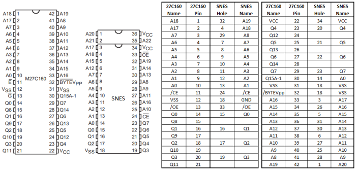
Anyway, follow the table, or use one of my adapter boards to do the rewiring for you.

Now, skip ahead to Step 10 to see if your hard work has paid off!
Step 9c: Install a 27C322 EPROM on the donor board
If you’re using one of the 27C322 adapters that I offer (either the compact or extended version), read the article linked there to see how to use it in your donor board. That article will also tell you how they work, if you want to make your own or wire it up by hand. If you’re using the SA-1 adapter board, then read the article there instead for details on how to use it.
If your cartridge only has a 32-pin slot, then you may be out of luck – your board may not support games larger than 8 Mbit. I recommend only making games that are 8 Mbit or smaller for PCBs with 32-pins. Because there are many variations of donor boards, I will not be going over how to expand the ROM space available past 8 Mbit on 32-pin SNES boards. If you still want to use a 27C322 to make an 8 Mbit or smaller game, though, just be sure to wire the top two address pins of the 27C322 (A19 and A20, pins 42 and 32, respectively) to GND. This will effectively cut the total space of the 27C322 down by a factor of 4.
Here’s an example of what one looks like with a compact 27C322 board attached.

Now that you’ve got your 27C322 attached to the board, you’re pretty much done! Head to Step 10 and we’ll finish up the game.
Step 9d: Install a 29F033 EEPROM on the donor board
If you are using the one 29F033 chip, assuming the game programmed correctly your life is comparatively easier at this step. Just plop your little adapter board into the place where the other ROM was. Make sure you’re putting in the chip in the correct orientation!

You need to make absolutely sure your game is programmed correctly before you solder it into the socket. You don’t want to spend all that extra time desoldering a chip you found out was programmed incorrectly! Once you’re sure, go ahead and secure the header pins with solder and trim the bottoms off. In the picture below, the top row is uncut, and the bottom row is cut.

You can see the difference! Be careful when you’re clipping these – you don’t want one to fly into your eyeball. This has happened to me. It is not pleasant. Clip them into a trash can or something.
If your game only has 32 pins for the socket, then you may be out of luck – your board may not support games larger than 8 Mbit. I recommend only making games that are 8 Mbit or smaller for PCBs with 32-pins. Because there are many variations of donor boards, I will not be going over how to expand the ROM space available past 8 Mbit on 32-pin SNES boards. If you still want to use a 29F033 to make an 8 Mbit or smaller game, though, just be sure to wire the top two address pins of the adapter board (A20 and A21, pins 1 and 2, respectively) to GND. This will effectively cut the total space of the EEPROM down by a factor of 4.
Now, go ahead and skip to Step 10.
Bonus: Install multiple 29F033 EEPROMs on the donor board (ExHiROM)
I’m only keeping this here for posterity – I saw this on NintendoAge a long time ago, and felt it should be preserved somewhere. This method requires you split your larger-than-32 Mbit game onto two EEPROMs, and is for HiROM donors with MAD-1 chips on them.
This process is not guaranteed to work with every game larger than 32 Mbits, only true ExHiROM games. ROM hacks and translations likely do not use true ExHiROM mapping, and should be made with a custom board.
The first thing you’ll need to do is remove your MAD-1 decoder from the PCB. Here’s what your board should now look like, and the components you’ll be using.

Bend up pin 13 on the MAD chip, and place it back into the board. If it’s easier for you, you can try just cutting the pin without removing the chip, but make sure you can still access pin 13 coming from the MAD-1 chip.

Now, remove pin 33 from the header on the FIRST EEPROM. This is the /OE (output enable) pin, which will be controlled by the MAD-1 chip. Put the EEPROM in the socket, making sure it’s in the correct orientation, and solder it in. Remember, you’ll be missing pin 33, so don’t solder anything on that. Do NOT trim the header pins on the back yet!
Now, you have one of two choices. If you want a cleaner looking assembly, remove the header pins on the SECOND EEPROM adapter board. Make sure all the solder is out of the holes, and place it on the back of the board on the header pins from the FIRST EEPROM, like a sandwich. Make ABSOLUTELY SURE the board is facing the exact same orientation as the first board so that pin 1 on “A” is connected to pin 1 on “B” and so on. You don’t want to put it in backwards or upside-down!!

If removing the header pins is too much of a pain for you (completely understandable), then you can connect each pin from EEPROMs “A” and “B” together with wires. But, make sure you do NOT wire the pin 33’s together!
Now, you should have a board with two TSOP adapter boards connected in parallel, either through wires or the sandwich method, with pin 33 disconnected to everything on both boards. You should also have a MAD-1 chip with a floating pin 13.
Connect pin 13 on the MAD-1 board to pin 35 on the TSOP adapter boards. Make sure both pin 35’s are connected! Then, run a wire from the “A” EEPROM pin 33 to pin 1 on the MAD-1 chip. Finally, run a wire from the “B” EEPROM pin 33 to pin 16 on the MAD-1 chip. Note that pin 1 and 16 on the MAD-1 chip are still in the board – this is because they’re not connected to anything on the board anyway, so we don’t have to pull them out. You can access them from the top of the board, or the back of the board. Here’s what it should look like afterwards (I used the sandwich method):


Now, you’re nearly done! Skip over to Step 10!
Step 9e: Populate your custom PCB
Using my custom SNES boards gives you a TON of options. The boards may look daunting, but it’s not too bad. I’ll try to split it up into discrete sections to make it easy to follow. Let me know if these explanations are confusing, and I’ll do my best to make it a bit easier to follow. Alternatively, you can view the pages on the Basic Board or Advanced Board separately.
If you’re using the Advanced Board, skip ahead to that section.
Basic Board
As mentioned previously, this board is good for affordable smaller games, or for replacing original SNES PCBs. There are two main modes you can use this board in, which I’ll be denoting with differently colored boxes.
Topside

Note that for every non-discrete part you use, there should be a corresponding ceramic capacitor. So, each of the red and purple boxes (except the battery, resistors, diodes, and transistor) should be accompanied by a 100 nF ceramic decoupling capacitor. This is ESPECIALLY important for the CIC. Furthermore, C1 is a 22 uF electrolytic capacitor that is needed for every game.
In general, for the logic chips (the 74 series parts) you can use either the 74HC, 74HCT, or 74LS versions of the parts. I have heard mixed things about using 74AC or 74ACT parts on old tech, so I avoid using these.
Parts required for every game (red boxes)
ROM: There are two sets of ROM sockets – the bottom set mimics the original SNES Mask ROM pinout and can also house the 27C801s (through the use of pads on the back, which will be explained in a bit), and the top set can use 27C160s for games up to 16 Mbit. ONLY use one set of these, not both. For whichever set you have parts for, use the bottom rows for LoROM games, and the top rows for HiROM games.
CIC/12F629: On the Basic board, there are sockets for either the original CIC, or the clone region lock-out chip, or SuperCIC. Only use one of these chips, not both! This will be required for the game to run on all un-modded SNESes. And be sure the decoupling capacitor is installed! If you’re using a 12F629 as a SuperCIC, and you didn’t get one pre-programmed, I’ll go over how to set one up at the bottom of this step. You can program these on the TL866.
Parts required for games that use SRAM (purple boxes)
Use all the parts boxed in red, as they are required for every game.
74xx139: Switches between data access on the ROM and the RAM. Pick one for either HiROM or LoROM. If you put both in, it’ll still work ok, but you only need to use one of them.
SRAM: Stores save data, as well as other useful information during gameplay. The 6264, 62256, and 1008 series of SRAM are supported – be sure to use low standby current versions to make your save games last as long as possible. You can lower the total amount of the SRAM the game sees by using pads on the back (detailed later) so just pick a chip that’s at least as large as your space requirements.
Resistors: Use the values marked next to the resistors. These are used mostly as part of the SRAM data retention circuit. There are pads for either through-hole or surface mount parts.
Diodes: Use diodes that have a low reverse leakage current – like the 1N4148. Lower reverse leakage current will increase the save battery life. Note that the black stripe should point to the right of the board. Polarity matters! Also, like the resistors, both through-hole and surface mount parts are supported.
Transistor: A 2N3904, 2N2222, or other equivalent NPN series of transistor. This is also part of the SRAM data retention circuit. Note that you only need to use one transistor, either a through-hole or a surface mount version.
CR2032: This is the coin cell battery that will retain your save data on the SRAM. I added holes for a lot of different battery holders.
Front solder pads (orange box)
For the topside, there is only one set of solder pads to worry about.
Decoder Bypass: Solder these only if you are making a game that does not utilize a 74xx139 in the purple boxes.
Now, to explain the backside.
Backside

Here’s how to configure the sets of solder pads on the back (though they are quite self-explanatory, in my opinion).
Pads required for every game (red boxes)
If you’re making a LoROM game, then solder the middle and lower pads together; if you’re making a HiROM game, then solder the middle and upper pads together.
If you’re using the bottom set of sockets for the ROM chip, then solder the two middle pads to the left to mimic the original SNES Mask ROM pinout; solder the two middle pads to the right to use a 27C801 instead. If you’re using a 27C160, you can ignore these pads.
Pads required for games that use SRAM (purple box)
The LoROM/HiROM pads are the same as the other groups of bank selection pads boxed in red, but the other SRAM pads need a bit of explanation.
SRAM Enable: The very left-most solder pads are marked “SRAM ENABLE”. If you are using SRAM, you must bridge this with solder. If you temporarily remove the solder while the SRAM is attached, the save data will be erased. You should do this if you change games on the same board. Don’t want garbage information coming from the SRAM to the new game.
SRAM Size Selection: Solder the pads accordingly to get the amount of SRAM your game uses. Follow the table to know which way to solder the pads. Here’s a reference table:

That should be all the parts and pads you need to take care of. Skip ahead to find out how to program the SuperCIC if you have a blank 12F629, or skip to Step 10 if you don’t.
Advanced Board
This board is useful for larger games and multicarts. There are three main modes you can use this board in, which I’ll denote with differently colored boxes. Note that the pictures below show an older version of the board, but any newer versions I offer aren’t going to be appreciably different, so the pictures will still be accurate.
“EX MODE” is used for single games larger than 32 Mbit, and will use ROM1 and ROM2 slots.
Topside
Note that for every non-discrete part you use, there should be a corresponding ceramic capacitor. So, each of the red, purple, and yellow boxes (except the battery, resistors, diodes, and transistor) should be accompanied by a 100 nF ceramic decoupling capacitor. This is ESPECIALLY important for the CIC. Furthermore, C1 is a 22 uF electrolytic capacitor that is needed for every game.
In general, for the logic chips (the 74 series parts) you can use either the 74HC, 74HCT, or 74LS versions of the parts. I have heard mixed things about using 74AC or 74ACT parts on old tech, so I avoid using these.
Parts required for every game (red boxes)
ROM1: The 27C160 or 27C322 EPROM that holds your ROM data that you prepared earlier. Use the bottom rows for LoROM games, and the top rows for HiROM games.
74xx257: Multiplexers that convert the 16-bit databus of the EPROM to the 8-bit bus of the SNES. This is the only part I really recommend using the HCT or LS version over the HC, but I’ve still had success with all of them.
74xx139: Enables the output of the multiplexers (also helps switch between ROM1 and ROM2, but that feature is only used in “EX MODE” or multicart mode). Note that this is the ‘139 located directly left of the bottom ‘257.
12F629: The clone region lock-out chip, or SuperCIC. This will be required for the game to run on all un-modded SNESes. Be sure the decoupling capacitor is installed! I’ll go over how to set one up at the bottom of this section, if you didn’t buy a pre-programmed one. You can program these on the TL866. Newer versions of the board also support surface mount versions of the part as well.
Parts required for games that use SRAM (purple boxes)
Use all the parts boxed in red, as they are required for every game.
74xx139: Switches between data access on the ROM and the RAM. Pick one for either HiROM or LoROM. If you put both in, it’ll still work ok, but you only need to use one of them. Note that this part is one of the ‘139s located directly left of the top ‘257, directly underneath the battery slot.
SRAM: Stores save data, as well as other useful information during gameplay. The 6264, 62256, and 1008 series of SRAM are supported – be sure to use low standby current versions to make your save games last as long as possible. You can lower the total amount of the SRAM the game sees by using pads on the back (detailed later) so just pick a chip that’s at least as large as your space requirements.
Note that if you are making a multicart, only 62256 and 1008 series of SRAM are supported, and you’ll need to kink out one of the legs of the SRAM chip to solder into the corresponding hole on the top of the board – pin 1 for 62256s, or pin 2 for 1008s.
Resistors: Use the values marked next to the resistors. These are used mostly as part of the SRAM data retention circuit. There are pads for either through-hole or surface mount parts.
Diodes: Use diodes that have a low reverse leakage current – like the 1N4148. Lower reverse leakage current will increase the save battery life. Note that the black stripe should point to the right of the board. Polarity matters! Also, like the resistors, both through-hole and surface mount parts are supported.
Transistor: A 2N3904, 2N2222, or other equivalent NPN series of transistor. This is also part of the SRAM data retention circuit. Note that you only need to use one transistor, either a through-hole or a surface mount version.
CR2032: This is the coin cell battery that will retain your save data on the SRAM. I added holes for a lot of different battery holders.
Parts required for games that use two ROM chips (yellow boxes)
This configuration is for EX MODE games, or for multicarts (up to 32 Mbit ROMs on each slot). Use all the parts boxed in purple and in red, in addition to the following:
ROM2: Holds either the second half of your larger-than-32-Mbit game, or the second ROM in the multicart. Program the same way you programmed ROM1 from earlier in the tutorial. And, like ROM1, use the bottom rows of sockets for LoROM games, and the top rows of sockets for HiROM games. Note that you must use the same mapping type on both sockets – you can’t use one LoROM and one HiROM ROM.
74xx74: Flip-flop that flips (or flops) between each ROM chip every time the reset button is pressed. Used for multi-carts (you don’t need it for EX MODE games).
Front solder pads (orange box)
For the topside, there is only one set of solder pads to worry about.
Decoder Bypass: Solder these only if you are making a game that does not utilize a 74xx139 in the purple boxes.
Now, to explain the backside.
Backside

There are a lot fewer solder pads on the back than there were on the old board. Here’s how to configure them (though they are quite self-explanatory, in my opinion).
Pads required for every game (red boxes)
Choose the pads accordingly for your game. If your game is larger than 32 Mbit, solder bridge the “EX MODE” pad to the middle. Note that you can only have one EX MODE game on a cartridge, since you’ll be using both ROM slots for that.
Also, if you are using a 27C322, you must choose either the HiROM or LoROM pads depending on the game you are making. The 27C160 pad covers both HiROM and LoROM.
Pads required for games that use SRAM (purple box)
The single game/multicart and HiROM/LoROM pads are self explanatory, but here’s a bit more background for the other sets.
SRAM Enable: The very left-most solder pads are marked “SRAM ENABLE”. If you are using SRAM, you must bridge this with solder. If you temporarily remove the solder while the SRAM is attached, the save data will be erased. You should do this if you change games on the same board. Don’t want garbage information coming from the SRAM to the new game.
SRAM Size Selection: Solder the pads accordingly to get the amount of SRAM your game uses. Follow the table to know which way to solder the pads. Here’s a reference table:
Pads required for games that use two ROM chips (yellow box)
Like the one for ROM1, solder the pads that correspond to the ROM option you have chosen.
That should be all the parts and pads you need to take care of. But for reference, here is a short explanation about how to program the SuperCIC. If you don’t need this, skip ahead to Step 10.
Programming the SuperCIC
Every SNES cartridge has a CIC chip to “unlock” the SNES to run the software on the cartridge. It interfaces with a CIC chip on the SNES console to check and make sure the region is correct. So any game we make is gonna need one itself. If you’ve got an extra one from an old game lying around, you can use that, but there’s a way to make one from a microcontroller. All we have to do is program a PIC12F629 with the “SuperCIC” code from the SD2SNES blog (based on the work from Segher at HackMii). Luckily, the MiniPro programmer we have has the capability to program the PIC. Follow the instructions on the site if you’re not sure how to program this correctly.

You shouldn’t run into too many problems, it’s a pretty simple process. If your game doesn’t immediately boot up, try pressing the reset button a few times to kick it to the correct region.
So now, you should have all the information you need to populate your board to get the results you want. Just finish putting your parts into their sockets, and you’re good to go!
Step 10: Finish your game
When you put your board back in the cartridge, you might have to clip the little plastic stand-off on the back of the cartridge, especially if you used the TSOP adapter board because that’s gonna get in the way. Also, some plastic tabs around the top might need cutting as well, if you’re using an extended adapter board or one of my custom boards – nothing too drastic.

Now close your game back up nice and tight. If you did everything right, you should be playing your game just fine! If not…. well here’s a few things you can try to fix it.
Troubleshooting tips
If you’re reading this section to fix a game, you should heed my earlier advice if you haven’t already, and invest in making a dedicated prototyping board with proper sockets for things like your EPROM. I have a few special boards set aside with these sockets so I can swap these chips in and out to test games before I solder them directly to the board. They are extremely handy. It’s pretty easy to make some test boards using my custom PCBs, so check them out if that sounds like something you’d like to try.
Here’s some tips you should follow before you give up (or ask me). This is the order I would try them in – it’s listed from shortest to longest amount of time to check. Please do these things before you message me or leave a comment, cause I’m gonna ask you if you did before anything else!!
- Check for any cold solder joints. They’ll be recognizable by their “misty” or “crumbly” appearance. To fix them, just heat them up (and make sure they’re heated sufficiently) and put some new solder on them.

- Also, make sure you didn’t miss any pins or wires. You’ll have a lot to solder, after all. It only takes a single pin to be disconnected to screw up the whole thing.
- Make sure your SNES works with other normal games. I know this sounds silly, but you never know if your SNES just kicked the bucket or not between games. I once bought Super Mario RPG and the sound didn’t work – but it wasn’t the game, it turns out my SNES audio fried since I last played!
- Check to make sure all your chips are in the correct orientation – especially for custom PCBs, where you have to provide many chips yourself.
- Check to make sure you didn’t cut any traces on the board accidentally – if you did, you’ll have to add a replacement wire.
- If you’re using a SuperCIC chip, try pressing the reset button five to ten times, and try power cycling the console as well. This will reset the region detection on it – your chip might be set to NTSC but it needs to be PAL, for example. (Also make sure the proper capacitors are present on the board around these chips).
- If you’re using a donor, did you remember to test the original game before you took the EPROM out? Maybe something else is damaged on the board, and it’s not your fault. Try replacing the capacitors (smaller ones are 0.1 uF, the large electrolytic is 22 uF). Clean the contacts that go into the SNES on the cartridge. Use like rubbing alcohol or something, look online for resources, I’m not good at housekeeping stuff.
- Finally, even if you THINK everything is connected correctly, use a multimeter and check the continuity of each pin on your EPROM or other chips to its destination. This means testing the cartridge connector in some cases. Follow the pin tables and/or schematics for the type of memory chip you chose up in Step 9. This is arduous – but any time I was stumped, I usually found that just one of the pins I thought was connected wasn’t in reality. Refer to this table below for the pinout of the cartridge – you only really have to test the address pins (A0 – A23), data pins (D0 – D7), GND and Vcc pins. Everything else should have been left alone.

If all else fails, you might have to desolder your chip, blank it, reprogram, and try again. Unfortunately, it’s hard to troubleshoot these boards sometimes.
Make a label
First things first, if you’re using an existing cartridge, you gotta get that old pesky label off of your game. You’re gonna want to just focus on the front cover, obviously. You can try to take the label off by hand, but I’ve never been able to get it completely off. Always get a ton of extra residue and paper.
I found a solution that works pretty well, though. All you have to do is mix equal amounts of baking soda and vegetable oil – you only need about a tablespoon. Rub it on all the leftover sticker and let it sit for half an hour. Afterwards, remove the rest of the sticky crap with something like isopropyl alcohol. Wash it off and you should have a blank canvas on which to work. I’ve also seen that soaking the cartridge in water for an hour or two will make the paper soft, and you can rub it off with your fingers.

Now, you need to get a new sticker for the front! You can either buy them online at various shops for $5 or $6, which might be the most convenient. That’s certainly the case for me. One shop I’ve bought labels from is Hondrus Label Shop (click the link for 10% off your order!). Here’s a picture of a Tales of Phantasia cart I made with labels from this store. It’s kind of a semi-gloss finish, but they’re very good quality and have a lot of cool alternate cover art.
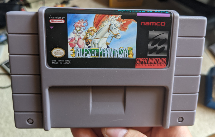
Or, you can print them yourself if you have a good enough printer (or if your game doesn’t actually have a label). It might be cheaper to just buy them individually if you’re not planning on making a whole lot of games. Maybe see if your local office supply stores sell these in single sheets or will print them on the paper for you?
If you want to make your own label, use this template. I found it on DeviantArt.

Then, you can use your favorite photo editing software (I prefer GIMP, which is a free Photoshop-esque program) to place your own picture and name. Search for pictures of your game on Google or something as a reference.
Now, you’ll want to make sure the size matches up for when you print them out. The SNES labels need to be approx. 1.77” x 3.25” when cut. I’m not a wizard at getting this to line up correctly, so you’re on your own for this.
You can use full page sticker sheets and cover them with lamination paper. It’s more economical to fill up a whole sticker sheet with labels, then cover it with a full sheet of lamination. Buying a full package of these sticker and lamination sheets can get a bit pricey, though. A suggestion from my friend mrTentacle is to print the label on vinyl sticker sheets, then spray them with a fixative. The sticker sheets he uses are similar to these and the finish material is similar to this.
Conclusion
It’s been a long time coming, but finally, you’ve completed your first SNES game!
Remember that selling reproductions of licensed games is illegal! I do not condone this! And don’t go to conventions trying to sell them, passing them off as legitimate! That’s called being a jerk. Don’t rip off genuine game collectors, we’re nice people. I can’t tell you how many times I’ve bought games on eBay or in a store that I thought was genuine, and it turned out to be a reproduction. It shouldn’t happen!
Hopefully this guide was comprehensive and detailed enough to give you a good understanding of what to do and why we did it. If any part is unclear, if I have any mistakes, or you need help figuring out your board, feel free to email me, and I will do my best to clarify or fix the problem! I still plan on continuously updating this tutorial but let me know what you wanna see most, and I’ll try to focus on that if there’s enough of a demand!
Until then, tinker on my fellow hobbyists!
I got a lot of my information from the NesDev forums and discord channel (RIP NintendoAge). Check them out – they’re amazing! Also, special thanks to Martin Samuelsson (mrTentacle) for his board and chip donations, as well as support, when I was first starting out, and for helping others in the comments section.
And if you’d like to purchase any of my materials, head over to the store page and I’ll be happy to hook you up!

[…] won’t go over how to do this here. Check out the main SNES tutorial if you are unsure how to get your ROM onto the 27C322. Be sure to verify the ROM is ready to […]
LikeLike
Hello,
I’m using your older 27C322 custom boards and they’re working great! The only problem I can’t fix is that resetting the games doesn’t work. While the game is running, pressing reset sends me to a black screen and it never loads the game. If I turn power off and back on, it works fine.
I’ve made 4 SMW ROM hacks on these boards and they all do this. It’s worth noting that I used one of your SNES to 27C322 extended adapter boards and put an SMW ROM hack on it and it works perfectly, reset included. Also, factory carts work in the console as expected.
Here’s a picture of one of my boards if it helps. https://imgur.com/gallery/Qw1rMNJ
I love your products and greatly appreciate all of the work you’ve put into this area!
LikeLike
I saw your duplicate comment on the other thread – I have my site set up so that I have to approve comments with links in them before they post, because I get a decent amount of spam so I want to make sure the comments with links are legit. So maybe that’s why you thought it was messed up haha
Anyway, wow, I haven’t seen those boards in a long time! Lol. All the new ones are green because it got too expensive to make white.
Looks like a great solder job though, very clean. The reset issue is strange… at least the game mostly works though, lol. Have you made any other games that have this issue, or is it just the SMW hack? One thing maybe to try is just removing that electrolytic capacitor on the right side of the board next to the SRAM. I don’t have those on my new boards, I decided they weren’t extremely necessary since the other electrolytic is on the board.
I noticed a while back when I was testing the boards myself with that capacitor in there that the voltage would jump above 5V sometimes on the SRAM after the game powers off – not a big issue, it’s certainly not going to damage anything, and I didn’t see any issues with the games I was testing at the time. I don’t know if that happens while resetting, either. But that’s the only thing different on the board from regular OEM cartridges.
LikeLike
Thanks for the quick reply! Each of the 4 other games I’ve made are all different SMW ROM hacks. The 3 others on the custom PCBs have the same issue, but the one on an original cart with the 27C322 extender board works fine. I did make a test board that’s identical to the custom PCBs aside from the headers, so I may load the hack that works on the extender board onto a 27C322 and test it there too.
I took out that electrolytic capacitor and had the same issue. Before that, I also tried removing the 2N2222 since you mentioned it in another comment. Same issue afterwards, and I put it back in.
It isn’t a huge deal, but it can be a bit annoying when trying to reset while doing speed runs.
LikeLiked by 1 person
Hmm what SMW rom hack is it? Maybe I can try it out myself on my newer boards
LikeLike
The one I’ve been working on is Super Dram World, but my carts with Quickie World 2, Grand Poo World, and Grand Poo World 2 all do the same thing.
LikeLike
Anyone might have an interest in my new supercic build (now for pic 12F683).
https://www.youtube.com/watch?v=CiqkBzIGKeg
Testers said it worked better than the 12F675), they say it worked well on the S-Famicom and SNES-Baby. You may also be interested in my new tool (it was made specifically for megadrive), but many functions can be used with SNES and other binary files. Here the link is interested in testing:
https://www.romhacking.net/utilities/1621/
LikeLike
Nice! I might have to pick up some chips and try this out. Thanks!!
LikeLike
Hi I’ve just finished soldering a simple 16 mbit 27C160 chip onto your basic custom board along with caps and supercic chip and jumped the lo rom pads as mentioned in the guide (there’s no SRAM or battery required as game uses passwords and has none on my original cartridge) I’ve tested the game but it’s a blank screen. The only thing I can think of is that when I programmed it the first bank programmed successfully and I moved onto the 2nd bank the programming failed at the first attempt because I had either as I think I had A18 or A19 in the wrong place by mistake, I then realised this, changed the switches to correct it and the 2nd bank was programmed successfully so I then did switches again for the 3rd and for the 4th, should I have started again with the first bank after the failure as I don’t think I did that?
LikeLike
Yeah you might have written over some of the data in the first bank, you should probably erase the whole chip and start again
LikeLike
Is there a parts list somewhere with maybe mouser links? I have the boards and eeproms, but unsure of what other parts should be purchased
LikeLike
Depends on which board you have. I have instructions for each of my own designed boards with a parts list. For some of them I have links to example parts too. A mouser cart isn’t a bad idea, I just need to make time to do make one lol
LikeLike
Will a normal Pic programmer, work on the eeprom? For example MX29L3211MC (Which I found more easily), will it be programable? What would be other options?
LikeLike
Oh by Pic programmer I mean the old K150 one. I was planning on using the pickit3 new one to program the new smd pic version, but I had this doubt about the eeprom. I was also looking for finalizing (it’s sitting here for years) My Sanni cart reader, maybe I could use that to flash the eeprom?
Thanks for all the info anyway.
LikeLike
I don’t know much about programming other kinds of chips, you’ll have to check in the programmers device list to see if it’s supported. I don’t believe a sanni has the ability to program UV EPROMs
LikeLike
Good idea, I’ll check that out. Looking at sanni wiki on github, they seem to be able to flash repros, I’ll give a go anyways. Thanks for the reply =)
LikeLike
hi, thought I’d ask if it’s possible to have 4 games on the one pcb that’s 2mb that you hex modify so 2+2, 2+2?
LikeLike
Hello! I was wondering if there are any flash IC alternatives to the 27C322 and others. I’d like to use all new parts, thank you!
LikeLike
I retract this comment, but I’d like to ask if there are other IC’s you know of that may be cheaper. Thank you again!
LikeLike